Read Sharp LC-20SD4E (serv.man2) Service Manual online
DISASSEMBLY INSTRUCTIONS
B1-2
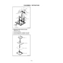
Fig. 1-4
Holder Ac Inlet
1
1
1
(A)
2
2
2 2
(B)
3
3
3
3 3
3
3
4
4
4
4
4
Operation PCB
Sacler PCB
4
4
4
Angle Earth-2
AV PCB
Back Light PCB
(C)
5
5
4
(D)
Tuner PCB
(E)
1-5:
1.
2.
3.
4.
2.
3.
4.
Remove the 3 screws
1
.
Remove the Holder PCB in the direction of arrow (A).
Remove the Back Shield in the direction of arrow (B).
Remove the LCD Panel in the direction of arrow (C).
Remove the Back Shield in the direction of arrow (B).
Remove the LCD Panel in the direction of arrow (C).
Fig. 1-5
1
Back Shield
1
Holder PCB
LCD Panel
Front Cabinel
(A)
(B)
(C)
1
HOLDER PCB/BACK SHIELD/LCD PANEL
(Refer to Fig. 1-5)
(Refer to Fig. 1-5)
B2-1
Masking Tape
(Cotton Tape)
(Cotton Tape)
DISASSEMBLY INSTRUCTIONS
2.
REMOVAL
IC
Put Masking Tape (cotton tape) around the Flat Package
IC to protect other parts from any damage.
(Refer to Fig. 2-1.)
IC to protect other parts from any damage.
(Refer to Fig. 2-1.)
1.
Fig. 2-1
NOTE
REMOVAL AND INSTALLATION OF
FLAT PACKAGE IC
FLAT PACKAGE IC
Some ICs on the PCB are affixed with glue, so be
careful not to break or damage the foil of each IC
leads or solder lands under the IC when removing it.
careful not to break or damage the foil of each IC
leads or solder lands under the IC when removing it.
NOTE
Masking is carried out on all the parts located within
10 mm distance from IC leads.
10 mm distance from IC leads.
Blower type IC
desoldering machine
desoldering machine
IC
Heat the IC leads using a blower type IC desoldering
machine. (Refer to Fig. 2-2.)
machine. (Refer to Fig. 2-2.)
2.
Fig. 2-2
NOTE
Do not rotate or move the IC back and forth , until IC
can move back and forth easily after desoldering the
leads completely.
can move back and forth easily after desoldering the
leads completely.
When IC starts moving back and forth easily after
desoldering completely, pickup the corner of the IC using
tweezers and remove the IC by moving with the IC
desoldering machine. (Refer to Fig. 2-3.)
desoldering completely, pickup the corner of the IC using
tweezers and remove the IC by moving with the IC
desoldering machine. (Refer to Fig. 2-3.)
3.
Blower type IC
desoldering
machine
desoldering
machine
IC
Fig. 2-3
Tweezers
Peel off the Masking Tape.
4.
Absorb the solder left on the pattern using the Braided
Shield Wire. (Refer to Fig. 2-4.)
Shield Wire. (Refer to Fig. 2-4.)
5.
NOTE
Do not move the Braided Shield Wire in the vertical
direction towards the IC pattern.
direction towards the IC pattern.
Braided Shield Wire
Soldering Iron
Fig. 2-4
IC pattern
B2-2
DISASSEMBLY INSTRUCTIONS
Supply soldering
from upper position
to lower position
from upper position
to lower position
IC
Supply the solder from the upper position of IC leads
sliding to the lower position of the IC leads.
(Refer to Fig. 2-6.)
sliding to the lower position of the IC leads.
(Refer to Fig. 2-6.)
2.
Fig. 2-6
Soldering Iron
Solder
IC
Absorb the solder left on the lead using the Braided
Shield Wire. (Refer to Fig. 2-7.)
Shield Wire. (Refer to Fig. 2-7.)
3.
Fig. 2-7
Soldering Iron
Braided Shield Wire
NOTE
Do not absorb the solder to excess.
IC
When bridge-soldering between terminals and/or the
soldering amount are not enough, resolder using a Thin-
tip Soldering Iron. (Refer to Fig. 2-8.)
soldering amount are not enough, resolder using a Thin-
tip Soldering Iron. (Refer to Fig. 2-8.)
4.
Fig. 2-8
Thin-tip Soldering Iron
NOTE
When the IC leads are bent during soldering and/or
repairing, do not repair the bending of leads. If the
bending of leads are repaired, the pattern may be
damaged. So, always be sure to replace the IC in this
case.
repairing, do not repair the bending of leads. If the
bending of leads are repaired, the pattern may be
damaged. So, always be sure to replace the IC in this
case.
Finally, confirm the soldering status on four sides of the
IC using a magnifying glass.
Confirm that no abnormality is found on the soldering
position and installation position of the parts around the
IC. If some abnormality is found, correct by resoldering.
IC using a magnifying glass.
Confirm that no abnormality is found on the soldering
position and installation position of the parts around the
IC. If some abnormality is found, correct by resoldering.
5.
Solder temporarily
Soldering Iron
INSTALLATION
Take care of the polarity of new IC and then install the
new IC fitting on the printed circuit pattern. Then solder
each lead on the diagonal positions of IC temporarily.
(Refer to Fig. 2-5.)
new IC fitting on the printed circuit pattern. Then solder
each lead on the diagonal positions of IC temporarily.
(Refer to Fig. 2-5.)
1.
Fig. 2-5
Solder temporarily
C-1
SERVICE MODE LIST
This unit is provided with the following SERVICE MODES so you can repair, examine and adjust easily.
To enter to the SERVICE MODE function, press and hold both buttons simultaneously on the main unit and on the remote
control for more than the standard time in the appropriate condition. (See below chart.)
control for more than the standard time in the appropriate condition. (See below chart.)
Initialization of factory TV data.
NOTE: If you set factory initialization, the memories are reset
NOTE: If you set factory initialization, the memories are reset
such as the channel setting, and the POWER ON total
hours.
hours.
POWER ON total hours are displayed on the screen.
Refer to the "PREVENTIVE CHECKS AND SERVICE INTERVALS"
(CONFIRMATION OF HOURS USED).
Refer to the "PREVENTIVE CHECKS AND SERVICE INTERVALS"
(CONFIRMATION OF HOURS USED).
Can be checked of the INITIAL DATA of MEMORY IC.
Refer to the "WHEN REPLACING EEPROM (MEMORY) IC".
Refer to the "WHEN REPLACING EEPROM (MEMORY) IC".
Set Key
Operations
Remocon
Key
VOL. DOWN
(Minimum)
1
2 sec.
Standard
Time
VOL. DOWN
(Minimum)
6
2 sec.
VOL. DOWN
(Minimum)
9
2 sec.
Set
Condition
TV mode
ALL mode
TV mode
Display of the Adjustment MENU on the screen.
Refer to the "ELECTRICAL ADJUSTMENT" (On-Screen Display
Adjustment).
Refer to the "ELECTRICAL ADJUSTMENT" (On-Screen Display
Adjustment).
POWER ON total hours can be checked on the screen. Total hours are displayed in 16 system of notation.
NOTE: If you set a factory initialization, the total hours is reset to "0".
1.
2.
3.
4.
2.
3.
4.
Turn on the POWER, and set to the TV mode.
Set the VOLUME to minimum.
Press both VOL. DOWN button on the set and Channel button (6) on the remote control for more than 2 seconds.
After the confirmation of POWER ON total hours, turn off the power.
Set the VOLUME to minimum.
Press both VOL. DOWN button on the set and Channel button (6) on the remote control for more than 2 seconds.
After the confirmation of POWER ON total hours, turn off the power.
Initial setting content of MEMORY IC.
POWER ON total hours.
= (16 x 16 x 16 x thousands digit value)
+ (16 x 16 x hundreds digit value)
+ (16 x tens digit value)
+ (ones digit value)
+ (16 x 16 x hundreds digit value)
+ (16 x tens digit value)
+ (ones digit value)
MICON Version
CONFIRMATION OF POWER ON TOTAL HOURS
ADDRESS
DATA
OEC7162A-083
INIT 0000 F8
LCD ON 0000
Check of the SUM DATA and MICON VERSION on the screen.
Refer to the "WHEN REPLACING EEPROM (MEMORY) IC".
Refer to the "WHEN REPLACING EEPROM (MEMORY) IC".
VOL. DOWN
(Minimum)
2 sec.
TV mode
2

