Read Sharp 66DW-18H (serv.man35) Technical Bulletin online
Sharp Electronics (UK) Limited
Originator AvW Supervisor Approval Date / / Reference SP84001X
Revision 2
White – Carry out as required, Yellow – Carry out as required and whenever the unit comes in for service, Red – Carry out on all units
CTV990107
Month of Issue: January 1999
Classification: White
TELEVISION TECHNICAL BULLETIN
Page 1 of 3
MODELS
66DW18H
REASON
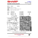
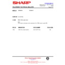
During production, the CRT has been changed from a Philips to a Thomson type.
ACTION
When replacing a Philips CRT for a Thomson one, carry out the following.
1. Replace the CRT.
2. Replace wires FH, FV and KC as indicated on the following pages.
3. Replace R609 with a 2.2R, 5% 2W resistor.
4. Replace C601 with a 8.2nF, 1.5kV capacitor.
5. Add a 4.7nF, 1.6kV capacitor in parrelel with C601. This is screen printed on the
2. Replace wires FH, FV and KC as indicated on the following pages.
3. Replace R609 with a 2.2R, 5% 2W resistor.
4. Replace C601 with a 8.2nF, 1.5kV capacitor.
5. Add a 4.7nF, 1.6kV capacitor in parrelel with C601. This is screen printed on the
top of the mother PWB as C633 (see page 9 of the service manual).
6. Remove SMD resistor R804.
7. On the CRT socket PWB, add two 100nF, 5% 63V capacitors, designated C1860
7. On the CRT socket PWB, add two 100nF, 5% 63V capacitors, designated C1860
and C1862 (see page 11 of the service manual – component side of the PWB).
When replacing a Thomson CRT for a Philips one, carry out the reverse of the above.
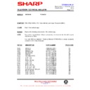
REF NO
DESCRIPTION
PART NUMBER
PRICE CODE
VB
66cm CRT, 16:9
VB66EGV2322*N
CT
KC
Wire lead
QCNW-2775BMZZ
AF
R609
Resistor, 2.2R, 2W
VRN-VV3DB2R2J
AA
C601
Capacitor 8.2nF, 1.5kV
RC-FZ0147BMZZ
AE
C633
Capacitor 4.7nF, 1.5kV
RC-FZ0148BMZZ
AD
C1860
Capacitor 100nf, 63V
RC-FZ9104BMNJ
AB
C1862
Capacitor 100nf, 63V
RC-FZ9104BMNJ
AB
Sharp Electronics (UK) Limited
Originator AvW Supervisor Approval Date / / Reference SP84001X
Revision 2
White – Carry out as required, Yellow – Carry out as required and whenever the unit comes in for service, Red – Carry out on all units
CTV990107
Month of Issue: January 1999
Classification: White
TELEVISION TECHNICAL BULLETIN
Page 2 of 3
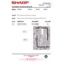
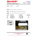
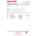
THOMSON PICTURE TUBE
Red Orange Yellow Green
FH lead FV lead
To change the deflection yoke wiring from a Philips CRT to a Thomson CRT, proceed as
follows.
follows.
1. Unsolder the red and orange FH leads from the deflection yoke.
2. Remove connector 1 from the yellow and green leads.
3. Strip the yellow and green wires of insulation (about 4mm).
4. Solder the red and orange (FH) leads as shown above.
5. Solder the yellow and green (FV) leads as shown above.
6. Replace
2. Remove connector 1 from the yellow and green leads.
3. Strip the yellow and green wires of insulation (about 4mm).
4. Solder the red and orange (FH) leads as shown above.
5. Solder the yellow and green (FV) leads as shown above.
6. Replace
lead
KC
(QCNW-2757BMZZ) connects the CRT socket to the neck of the CRT
with QCNW-2775BMZZ type.
FV
FH
KC lead
Sharp Electronics (UK) Limited
Originator AvW Supervisor Approval Date / / Reference SP84001X
Revision 2
White – Carry out as required, Yellow – Carry out as required and whenever the unit comes in for service, Red – Carry out on all units
CTV990107
Month of Issue: January 1999
Classification: White
TELEVISION TECHNICAL BULLETIN
Page 3 of 3
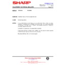
PHILIPS CRT Original deflection yoke PWB shown on left
CONNE
Connector 1
Orange Yellow Green Yellow Green
Red Red Orange
Red Red Orange
To change the deflection yoke wiring from a Thomson CRT to a Philips CRT, proceed as
follows
follows
1. Unsolder both the green and yellow (FV) and red and orange (FH) leads from the
deflection yoke PWB.
2. Solder these leads to the Philips CRT as shown above.
3. Replace wire KC (QCNW-2775BMZZ) that connects from the CRT socket PWB to the
3. Replace wire KC (QCNW-2775BMZZ) that connects from the CRT socket PWB to the
neck of the CRT with lead QCNW-2757BMZZ.
FV
FH
KC lead

