|
|
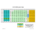
51AT-15H (serv.man2)
NVM location values
Service Manual
|
1
|
14.69 KB
|
|
|
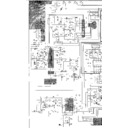
51AT-15H (serv.man3)
51AT15H circuit diagram
Service Manual
|
3
|
1.61 MB
|
|
|
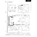
51AT-15H (serv.man4)
51AT15H PWB layout
Service Manual
|
3
|
3.23 MB
|
|
|
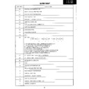
51AT-15H (serv.man5)
51AT15H NVM Map
Service Manual
|
4
|
235.36 KB
|
|
|
51AT-15H (serv.man6)
51AT15H adjustment procedures and child lock resetting details
Service Manual
|
3
|
262.47 KB
|
|
|
51AT-15H (serv.man9)
Quick set up guide
User Guide / Operation Manual
|
6
|
333.09 KB
|
|
|
51AT-15H (serv.man8)
User Guide / Operation Manual
|
18
|
400.13 KB
|

|
51AT-15H (serv.man31)
NVM Data
Firmware
|
|
283 B
|
|
|
51AT-15H (serv.man7)
51AT15H spare parts list
Parts Guide
|
4
|
377.75 KB
|
|
|
51AT-15H
51AT15H from the
Specification
|
1
|
21.3 KB
|
|
|
51AT-15H (serv.man21)
Countermeasures for various vertical stage problems. This Technical Bulletin includes vertical stage voltages and waveforms not given in the .
Technical Bulletin
|
4
|
76.56 KB
|
|
|
51AT-15H (serv.man29)
Change of the flyback transformer to include the EHT wire
Technical Bulletin
|
1
|
10.29 KB
|
|
|
51AT-15H (serv.man28)
Correction of part number for C0601
Technical Bulletin
|
1
|
6.33 KB
|
|
|
51AT-15H (serv.man27)
Resetting of child lock - details of NVM locations
Technical Bulletin
|
1
|
7.37 KB
|
|
|
51AT-15H (serv.man26)
Data change when replacing the NVM - OSD shift, language and child lock functions
Technical Bulletin
|
1
|
8.21 KB
|
|
|
51AT-15H (serv.man25)
Resetting of the child lock mode - simple instructions
Technical Bulletin
|
1
|
22.36 KB
|
|
|
51AT-15H (serv.man24)
Common faults on the 5BSA chassis
Technical Bulletin
|
1
|
18.14 KB
|
|
|
51AT-15H (serv.man23)
Change of tuner type (fitting instructions)
Technical Bulletin
|
3
|
824.54 KB
|
|
|
51AT-15H (serv.man22)
Details of how to place the receiver in Hotel Mode
Technical Bulletin
|
1
|
18.43 KB
|
|
|
51AT-15H (serv.man20)
Countermeasure for doming at high beam current
Technical Bulletin
|
1
|
6.95 KB
|
|
|
51AT-15H (serv.man19)
Countermeasure for intermittent no sound and or picture
Technical Bulletin
|
1
|
7.24 KB
|
|
|
51AT-15H (serv.man18)
Countermeasure for jittering teletext
Technical Bulletin
|
1
|
9.79 KB
|
|
|
51AT-15H (serv.man17)
Countermeasure for intermittent failure of Q602 (line output transistor)
Technical Bulletin
|
1
|
9.7 KB
|
|
|
51AT-15H (serv.man16)
Countermeasure for tuner drift
Technical Bulletin
|
1
|
15.32 KB
|
|
|
51AT-15H (serv.man15)
Line fold over, normally to one side of screen.
Technical Bulletin
|
1
|
34.18 KB
|
|
|
51AT-15H (serv.man14)
Too little green in the OSD and teletext displays.
Technical Bulletin
|
1
|
33.99 KB
|
|
|
51AT-15H (serv.man13)
Too much red or colour bleeding in the OSD and teletext displays.
Technical Bulletin
|
1
|
35.87 KB
|
|
|
51AT-15H (serv.man12)
Various error on the circuit diagram.
Technical Bulletin
|
1
|
36.19 KB
|
|
|
51AT-15H (serv.man10)
Intermittent failure to turn on
Technical Bulletin
|
1
|
14.67 KB
|
|
|
51AT-15H (serv.man30)
Packaging Weights Data
Regulatory Data
|
1
|
4.35 KB
|

