Read Sharp 51AT-15H (serv.man11) Technical Bulletin online
CTV2000 08 13
Month of Issue: August 2000
Classification:
White
TELEVISION TECHNICAL BULLETIN
Page 1 of 2
Sharp Electronics (UK) Limited
Reference AVW04082000-4
Revision 1
White Carry out as required
Yellow Carry out as required and whenever the unit comes in for service
Red Carry out on all units
MODELS
51AT15H
SYMPTOM Various physical circuit changes.
CAUSE
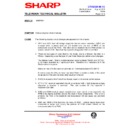
The following physical circuit changes are apparent on this chassis:
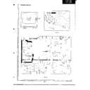
1. D619 and R632 (turn off voltage supply for the line output transistor - Q601) are
encased within a plastic tube and are tacked onto one end of R602 on the
component side of the PWB. The other end is inserted into the PWB where it is
screen printed C620. Note that the capacitor designated C620 is not fitted.
2. There are two types of tuner fitted to this model, one is a Mitsumi the other is a
Philips. Depending upon the type of tuner fitted, there are certain circuit changes.
The Mitsumi tuner - fitted to models between serial numbers 750320 and 767183 -
is no longer available as a spare part item. Therefore it is necessary to fit the
Philips tuner in its place.
Notes on how to fit this tuner are provided on Technical Bulletin CTV990115.
In some cases the Mitsumi tuner has been fitted to models outside of the serial
range above if the unit has failed after leaving the factory.
3. D1002 is located at the front of the chassis, near to the remote control sensor.
4. C713 (-10V reservoir capacitor) should be replaced with a high temperature type
whenever a receiver is serviced. The part number for this capacitor if
VCEAHA1CN108M.
5. Q502 and Q504 (vertical output transistors) run warm and it is not unusual for the
PWB to be slightly scorched around the base of these components. This is not a
problem, the PWB is fire retardant and discoloration will not cause any untoward
problems.
6. D509 and R509 (+5Vb feed into the base of Q507 - vertical stage) have been
connected in series and occupy the position of R509 screen printed on the
component side of the PWB.
CTV2000 08 13
Month of Issue: August 2000
Classification:
White
TELEVISION TECHNICAL BULLETIN
Page 2 of 2
Sharp Electronics (UK) Limited
Reference AVW04082000-4
Revision 1
White Carry out as required
Yellow Carry out as required and whenever the unit comes in for service
Red Carry out on all units
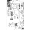
Note that on the schematic diagram D509 is designated R509.
7. On some chassis a resistor is added in series with the +5Va supply line. It is a
safety component designated R731 (in position J198) and is a 2R2 0.5W resistor.
8. On some chassis there is an extra resistor fitted in parallel with D506. This is a
3K3 0.25W resistor designated R522.
Display

