Read Sharp 21KF-80 (serv.man5) Service Manual online
6
21KF-80H
ADJUSTMENT PROCEDURES
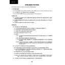
Service Mode function
All required adjustments for servicing this TV set, may be done in “service mode”, excepting G2 and FOCUS.
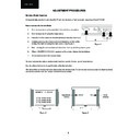
How to access the Service Mode
1.
Turn the receiver on and ensure that it is tuned into a test pattern.
2.
Turn the receiver off using the mains switch.
3.
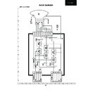
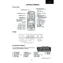
Press the volume down and channel up buttons together. See Fig.1.
4.
Continue pressing the volume down and channel up buttons while
turning the mains on using the mains switch. See Figure 1.
turning the mains on using the mains switch. See Figure 1.
5.
Keep pressing the volume down and channel up buttons until the picture appears.
6.
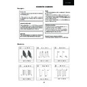
When <<SHARPX X VXX.XX>> appears on the screen, release the two buttons.
7.
The receiver is now in the service mode.
To move between the various service mode functions, use the channel up and down buttons.
Use the volume buttons to change the data to the desired value.
The data will be stored automatically when exiting the service mode. To exit the service mode press the stand-by button
the remote control or turn the receiver off with the mains switch.
the remote control or turn the receiver off with the mains switch.
XXXX:
Adjustment
(Yellow)
(Yellow)
Value
(Green)
(Green)
Figure 2
Figure 3
SHARP X X VXX.XX
STS0: XXXX XXXX
STS1: XXXX XXXX
STS2: XXXX XXXX
STS1: XXXX XXXX
STS2: XXXX XXXX
XX:
Figure 1
MENU CH
3
4
7
21KF-80H
Service adjustment and data list
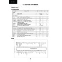
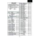
The table below shows the various service mode positions, range of values and default value. The columns are headed
as below.
as below.
Heading:
Descriptions:
OSD
This is what will appear on the screen at this position.
Function
This is the description of the mode’s function.
Range
This is the range of values that can be entered while in this mode.
Initial
This is the initial value, i.e. just after changing the NVM. Shadowed values are those to be modified in
Default.
Default.
Default
This is the recommended default value for this model.
FIX/ADJ
If this is ADJ, then it may be necessary to adjust this value away from the default.
No. OSD
Function
Range
Initial
Default
FIX/ADJ
1
AGC
AGC Take Over Point
0...63
34
34
ADJ
2
V-LIN
Vertical Slope [VS]
0...63
33
33
ADJ
3
V-AMP
Vertical Amplitude [VA]
0...63
18
18
ADJ
4
V-CENT
Vertical Shift [VSH]
0...63
17
17
ADJ
5
H-CENT
Horizontal shift [HS]
0...63
34
34
ADJ
6
H-CENT60
offset to H-CENT for 60 Hz
0...31 data(-16..+15)
20
20
FIX
7
EW / /
Horizontal Parallelogram [HP]
0...63
32
32
FIX
8
HB
Horizontal Bow
0...63
32
32
FIX
9
S-COR
S-Correction [SC]
0...63
22
30
FIX
10 DRI-RS
White point Red Standard white temp.
0...63
42
42
ADJ
11 DRI-GS
White point Green Standard white temp. 0...63
42
42
ADJ
12 DRI-BS
White point Blue Standard white temp
0...63
42
42
ADJ
13 DRI-RW
White point Red Warm white temp.
0...32
16
16
FIX
14 DRI-GW
White point Green Warm white temp.
0...32
9
9
FIX
15 DRI-BW
White point Blue Warm white temp.
0...32
9
9
FIX
16 DRI-RC
White point Red Cold white temp.
0...32
9
9
FIX
17 DRI-GC
White point Green Cold white temp.
0...32
9
9
FIX
18 DRI-BC
White point Blue Cold white temp.
0...32
16
16
FIX
19 SUB-VOL
Max Volume
0...63
60
60
FIX
20 SUB-CON
Sub Contrast
0...63
63
63
FIX
21 SUB-COL
Sub Colour
0...63
25
25
FIX
22 SUB-BRI
Sub Brightness
0...63
34
34
FIX
23 TINT
Sub Tint
0...63
32
32
FIX
24 SUB-SHP
Sub Sharpness
0...63
11
25
FIX
25 HTL-VOL
Max Hotel Volume
0...63
30
30
FIX
8
21KF-80H
No. OSD
Function
Range
Initial
Default
FIX/ADJ
26 HTL-PRG
Hotel Program number
0...99 or > 99 for none
255
255
FIX
27 RGB
OSD RGB Reference
0...15
0
0
FIX
28 SEARCH-SYS Sound system for auto tuning
0(L-BG),1(BG),2(I),3(DK)
1
2
FIX
29 CUT-R
Black Level off-set R [BLR]
0...63
0
0
FIX
30 CUT-G
Black Level off-set G [BLG]
0...63
10
24
FIX
31 CDL
Cathode Drive Level [CL]
0...15
5
5
FIX
32 DL-PT
Y-Delay time for PAL (TV) [YD]
0...15
4
4
FIX
33 DL-ST
Y-Delay time for SECAM (TV) [YD]
0...15
8
8
FIX
34 DL-4T
Y-Delay time for N443 (TV) [YD]
0...15
8
8
FIX
35 COL-OP
COLOUR OFFSET (PAL)
0...15
8
8
FIX
36 COL-OS
COLOUR OFFSET (SECAM)
0...15
8
8
FIX
37 COL-O4
COLOUR OFFSET (NTSC443)
0...15
4
4
FIX
38 SHP-OP
SHARPNESS OFFSET(PAL)
0...15
8
8
FIX
39 SHP-OS
SHARPNESS OFFSET(SECAM)
0...15
4
4
FIX
40 SHP-O4
SHARPNESS OFFSET(NTSC443)
0...15
8
8
FIX
41 SC-VOL
SCART volume
0..255
109
109
FIX
42 PRE-SC
Prescaler SCART input
0..127
25
25
FIX
43 PRE-FM
Prescaler FM/AM
0..127
72
72
FIX
44 PRE-NICAM
Prescaler SCART input
0..127
90
90
FIX
45 PRE-M
Prescaler SCART input for LL’ mono
0..127
3
0
FIX
46 AVC-DKY
AVC Decay
0...3 data (1.2.4.8.)
1
1
FIX
47
AC-OFF-TIM
Time to set the AC-OFF
0...15
0
0
FIX
timer is in steps of 10 minutes
48 DISP
Language or symbols
0(symbols),
0
1
FIX
1(English),
2(French)
2(French)
49 TXT-EUR
Teletext pan-European language
0 (pan-europe)
0
0
FIX
1 (cyrillic)
2(Greek)
2(Greek)
50 BKS
Black Stretch
0 (disable) or 1 (enable)
1
1
FIX
51 AVC
Automatic Volume Control(AVL)
0 (disable) or 1 (enable)
1
1
FIX
52 FFI
Fast Filter IF-PLL
0 (disable) or 1 (enable)
0
0
FIX
53 ACL
Auto Colour Limit
0 (disable) or 1 (enable)
1
1
FIX
54 S-L
Sound system L
0 (disable) or 1 (enable)
0
0
FIX
55 S-DK
Sound system DK
0 (disable) or 1 (enable)
1
0
FIX
56 S-I
Sound system I
0 (disable) or 1 (enable)
1
1
FIX
57 S-BG
Sound system BG
0 (disable) or 1 (enable)
1
0
FIX
58 BLUE-BACK
Video mute at Ident loss
0 (disable) or 1 (enable)
1
1
FIX
59 VMC
Video Mute at program/source Change
0 (disable) or 1 (enable)
1
1
FIX
60 HTL
Hotel mode
0 (disable) or 1 (enable)
0
0
FIX
61 BTSC
Reduced FM demodulator Gain (for BTSC sig)
0 (disable) or 1 (enable)
0
0
FIX
62 AV
Number of external AV sources
0 for 1 AV or 1 for 2 AV
0
0
FIX
63 FMWS
FM Window Selection
0 (disable) or 1 (enable)
0
0
FIX
64 SM0
Sound Mute bit 0
0 (disable) or 1 (enable)
1
1
FIX
65 SM1
Sound Mute bit 1
0 (disable) or 1 (enable)
0
0
FIX
66 AGC0
IF AGC speed bit0
0 (disable) or 1 (enable)
1
1
FIX
67 AGC1
IF AGC speed bit1
0 (disable) or 1 (enable)
0
0
FIX
68 FOA-FE
Phi 1 time constant for FE(RF)
0 (disable) or 1 (enable)
0
0
FIX
69 FOB-FE
Phi 2 time constant for FE(RF)
0 (disable) or 1 (enable)
0
0
FIX
70 FOA-AV
Phi 1 time constant for AV
0 (disable) or 1 (enable)
1
1
FIX
71 FOB-AV
Phi 2 time constant for AV
0 (disable) or 1 (enable)
1
1
FIX
72 TXT
Teletext
0 (disable) or 1 (enable)
1
1
FIX
73 TXT-WE
Teletext Western or Eastern characters
0 (western) or 1 (eastern)
0
0
FIX
74 FSL
Forced V-SYNC slicing level
0 (disable) or 1 (enable)
0
0
FIX
75 HP2
Sync of OSD
0 for Ph1 or 1 for Ph2
0
0
FIX
76 CP
Charge pump
0 (fast tuning) or
0
0
FIX
1 (moderate)
77 NICAM
NICAM decoding enabled
0 (disable) or 1 (enable)
1
1
FIX
78 IGR
IGR decoding enabled
0 (disable) or 1 (enable)
1
1
FIX
79 AUTO
Start auto tuning at POWER-ON
0 (disable) or 1 (enable)
0
0
FIX
80 TXT-TGL
Function of TXT key
0 or 1
0
0
FIX
81 EVG
Enable Vertical Guard
0 (disable) or 1 (enable)
1
1
FIX
9
21KF-80H
Screen adjustment
1. G2 Adjustment
1.
Enter the service mode (see page 6).
2.
Use the channel up or channel down buttons to enter the << BLUE-BACK >>
function.
3.
Set this to << BLUE-BACK: 0 >>, i.e. blue background is turned off.
4.
Turn the set off at the mains.
5.
Turn the set back on.
6.
Set the picture control settings to normal.
7.
Select the SCART input by pressing the TV/SCART button on the remote con-
trol. Do not connect an input to the SCART socket. A blank raster will appear.
trol. Do not connect an input to the SCART socket. A blank raster will appear.
8.
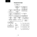
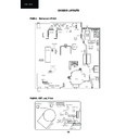
Connect an oscilloscope to TP851 on the CRT PWB. The waveform as in fig-
ure 4 should be displayed.
9.
Adjust the G2 control (screen voltage) so that the peak of this waveform is 3.5V
+/-0.1V above the zero volt line.
10. Enter the service mode.
11. Turn the blue background function back on again - set << BLUE-BACK: 1 >>.
12. Turn off the receiver using the mains button.
13. The G2 adjustment is now complete.
2. Focus Adjustment
1.
Receive a monoscope pattern signal at a level of 60 to 80 dB
µV.
2.
Set the picture settings to normal.
3.
Adjust the focus potentiometer to obtain maximum definition.
AGC Adjustment
1.
Tune the receiver into a colour bar signal on channel I-42.
2.
Set the RF generator to an output signal strength of 59 dB/
µV (+/-1dBµV) –75 Ohms.
3.
Connect an oscilloscope to TP201. TP201 is one end of R201.
4.
Enter the service mode (see page 6).
5.
Use the channel up and channel down buttons to enter the AGC mode.
6.
By using the volume up and the volume down buttons, adjust the AGC until the voltage on TP201 drops by 0.1V
to 0.3V below its maximum value.
to 0.3V below its maximum value.
7.
Change the input signal strength to 66-70dB
µV and make sure that there is no noise apparent in the picture.
8.
Turn the receiver off at the mains, this will exit the service mode and store the adjustment.
5
Figure 4

