Read Sharp XV-Z7000 (serv.man5) Service Manual online
33
XV-Z7000U/E
AN-Z7T
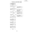
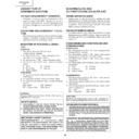
TROUBLE SHOOTING TABLE
YES
YES
NO
Checking the basic
performance
Is the POWER LED on or
flickering in red or green?
flickering in red or green?
Go to "Checking the
power unit"
power unit"
Go to "Checking the lamp
light-up"
light-up"
NO
Is the set turned on by the
set’s or remote controller’s
power key?
set’s or remote controller’s
power key?
Go to "Checking the
microcomputer
peripherals" and
"Checking the PLL circuit"
microcomputer
peripherals" and
"Checking the PLL circuit"
NO
Go to "Checking the
output line"
output line"
Go to "Checking the RGB
input"
input"
Go to "Checking the
component input"
component input"
Go to "Checking the
video input"
video input"
Go to "Checking the
audio input"
audio input"
Go to "Checking the RS-
232C"
232C"
End
NO
Is the cooling fan
running? Is the lamp on?
running? Is the lamp on?
Is the user menu
displayed?
displayed?
YES
YES
34
XV-Z7000U/E
AN-Z7T
YES
YES
YES
YES
YES
NO
Checking the power unit
Are the connectors CN751,
P1707 and P3701 inserted
completely?
P1707 and P3701 inserted
completely?
Insert the connectors
CN751, P1707 and
P3701 tightly?
CN751, P1707 and
P3701 tightly?
Replace the bimetal
Close the lamp cover
tightly.
tightly.
NO
Is the lamp cover closed
completely?
completely?
NO
Replace F701.
NO
Check Q706, Q708 and
Q710 for damage.
Replace as required.
Q710 for damage.
Replace as required.
NO
Is the bimetal switch off?
Is AC voltage (100-240V)
applied between pins (1)
and (3) of CN703?
applied between pins (1)
and (3) of CN703?
Disconnect the CN751
connector (EA). Is there
13V output at pins (7), (8)
and (9)?
connector (EA). Is there
13V output at pins (7), (8)
and (9)?
Check the output PWB for
short-circuit. Check also
the UNT3701 on the
connection terminal PWB
and its peripheral circuits.
short-circuit. Check also
the UNT3701 on the
connection terminal PWB
and its peripheral circuits.
35
XV-Z7000U/E
AN-Z7T
YES
YES
YES
YES
YES
YES
YES
NO
Checking the
microcomputer
peripherals
Is a voltage of about 3V
applied to pin (33) (RCS)
of IC1601?
applied to pin (33) (RCS)
of IC1601?
Check the intake filter
cover for poor fitting and
the cooling fan for trouble.
cover for poor fitting and
the cooling fan for trouble.
Check IC1601, IC1606 and
their peripheral circuits.
their peripheral circuits.
Is the signal level at pin
(7) of IC8037 about 0V?
(7) of IC8037 about 0V?
End
End
Set SW1602 to
"NORMAL" position.
"NORMAL" position.
NO
Is SW1602 set at
"NORMAL" position?
"NORMAL" position?
NO
NO
Check IC8018, IC8019,
IC8020 and their peripheral
circuits as well pin (26) of
IC1601 and its peripheral
circuits.
IC8020 and their peripheral
circuits as well pin (26) of
IC1601 and its peripheral
circuits.
Check IC8021 and
IC8022. Replace the PC
interface as required.
IC8022. Replace the PC
interface as required.
NO
NO
Check all the ICs
connected with the
SDA3/SCL3 and
SDA5/SCL5 lines.
connected with the
SDA3/SCL3 and
SDA5/SCL5 lines.
NO
Is there pulse signal at
pin (64) of IC1601?
pin (64) of IC1601?
Is there pulse signal at pin
(1) of IC1601?
(1) of IC1601?
Is there signal at pins (1),
(3), (4) and (6) of IC1802?
(3), (4) and (6) of IC1802?
Check all the signals (A1
thru A17 and D1 thru D15)
of IC8021 with oscilloscope.
Are signal levels 0V and
3V?
thru A17 and D1 thru D15)
of IC8021 with oscilloscope.
Are signal levels 0V and
3V?
36
XV-Z7000U/E
AN-Z7T
YES
YES
YES
YES
YES
Checking the lamp
light-up
Turn on the power switch.
Is discharge sound heard
from the lamp?
Is discharge sound heard
from the lamp?
Insert the BA harness
tightly. Or replace it as
required.
tightly. Or replace it as
required.
Go to "Checking the
power unit".
power unit".
Replace the ballast unit.
NO
Go to "Checking the
microcomputer
peripherals".
microcomputer
peripherals".
NO
NO
Are DC260-400V voltages
applied between the pins
of PL connector?
applied between the pins
of PL connector?
NO
Replace the lamp.
NO
Is the lamp socket
disconnected?
disconnected?
Reconnect the lamp
socket tightly.
socket tightly.
Is the BA harness tightly
inserted? Is the harness
broken?
inserted? Is the harness
broken?
Is voltage of over 1V
applied between pins (1)
and (2) of BA harness?
applied between pins (1)
and (2) of BA harness?
YES
YES
YES
NO
Checking the PLL circuit
Is there 120MHz clock
output at pin (8) of
IC8001?
output at pin (8) of
IC8001?
IC8001 or its peripheral
circuit defective.
circuit defective.
End
NO
Is there 40MHz clock
output at pin (9) of
IC8001?
output at pin (9) of
IC8001?
NO
Is there 16MHz or so
clock output at pin (7) of
IC8001?
clock output at pin (7) of
IC8001?

