Read Sharp XV-Z3100 (serv.man2) Service Manual online
XV-Z3100U/XV-Z3100/XV-Z3300/DT-510
2 – 1
XV-Z3100U
Service Manual
CHAPTER 2.
REMOVING OF MAJOR PARTS
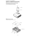
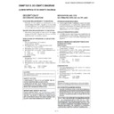
[1] Removing the lamp door and the lamp unit
1. Loosen the lamp door fixing screw. Lift off the lamp door.
2. Remove 2 lamp unit fixing screws to detach the lamp unit.
[2] Removing the top body
1. Remove 8 top body fixing screws to detach the Top body.
1
2
2
Lamp Door
Lamp Unit
1
1
Top Body
Bottom Body
XV-Z3100U/XV-Z3100/XV-Z3300/DT-510
2 – 2
[3] Removing the main PWB unit and rear RC receiver PWB Unit
1. Remove 1 Rear RC receiver PWB fixing screws to detach the Rear RC receiver PWB unit.
2. Remove all connectors from the main PWB unit.
3. Remove 4 terminal fixing screws.
4. Remove 3 main PWB fixing screws to detach the main PWB unit.
[4] Removing the fan and power/ballast ass'y
1. Remove 2 fans for the power supply ballast unit and 1 fan for the optical mechanism unit.
2. Remove 2 bimetal fixing screws to detach the bimetal.
3. Remove 2 lamp socket fixing screws to detach the lamp socket.
4. Remove 1 AC inlet fixing screw.
5. Remove 4 ballast unit fixing screws to detach the power/ballast ass'y.
6. Remove 4 ballast shield (upper) fixing screws to detach the ballast shield (upper).
7. Remove 2 ballast PWB fixing screws and 1 clip to detach the power/ballast ass'y from the ballast shield (lower).
[RC-F]
[IR1]
[IR2]
[US]
[SO]
[FB]
[EA]
[RC-R]
[FC]
[FD]
4
2
[CW]
[FA]
[LF]
[MO]
[BB]
3
1
A
A
MAIN PWB Unit
Rear RC
Receiver
PWB Unit
7
6
6
7
Power/Ballast
Ass'y
Ballast shield (upper)
Ballast
shield
(lower)
1
4
3
5
2
Bimetal
Fan for
optical
mechanism
unit
Fans for power supply
ballast unit
Lamp Socket
Power /Ballast Ass'y
XV-Z3100U/XV-Z3100/XV-Z3300/DT-510
2 – 3
[5] Removing the optical mechanism unit and front RC receiver PWB
1. Remove 4 optical mechanism unit fixing screws to detach the optical mechanism unit.
2. Remove the RC PWB unit.
[6] Removing the photosensor PWB unit, blower fan, DMD PWB, and DMD
1. Remove 1 photosensor PWB fixing screw to detach the photosensor PWB.
2. Remove 2 blower fan fixing screws to detach the blower fan.
3. Remove 4 DMD heatsink fixing screws to detach the DMD PWB unit and the DMD.
1
2
RC PWB Unit
Optical Mechanism Unit
1
2
3
Optical Mechanism Unit
Photosensor PWB Unit
DMD
DMD heatsink
DMD spring
Backer plate
DMD PWB Unit
DMD socket
Blower fan

