Read Sharp XV-Z200E (serv.man6) Service Manual online
8
XV-Z200U/E, XV-Z201E
DT-300
DT-300
OPERATION MANUAL
Pr
o
jec
tor
(F
ro
n
t a
nd
T
o
p
V
iew)
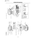
Part Names
POWER indicator
Exhaust ventilative hole
LAMP indicator
TEMPERA
TURE
W
ARNING indicator
ADJUSTMENT buttons
()
UNDO button
MENU button
RESIZE button
INPUT button
Swivel Stand
LOCK/UNLOCK lever
Remote contr
o
l sensor
Lens cap
Zoom knob
Exhaust ventilative hole
Focus ring
Lens shift dial
ENTER button
KEYSTONE button
ON button
ST
ANDBY
button
PICTURE SETTING button
Attac
h
ing the Lens Cap
The lens
cap can be attac
hed to the
pr
ojector using commer
cially
availa
ble straps
(for
cellul
ar phones
etc.), as shown in the figur
e.
Pr
o
jec
tor
(S
ide
an
d R
ear
V
iew)
"
/'
/\
/|
Pr
o
jec
tor
(R
ear
V
iew)
Using the
T
e
rminal Co
ver
When the projector is used on a desktop
, high mounted or ceiling
mounted, attach the ter
m
inal co
v
e
r (supplied)
to hide the connecting cab
les
.
Attac
h
ing the
T
e
rminal
Co
ver
1
Align with the tabs on
the projector and
then press the
ter
m
inal co
v
e
r in the
direction of
the arro
w
.
2
Tighten the
tw
o
scre
ws on the bottom
of the projector
.
Remo
ving the
T
e
rminal
Co
ver
1
Loosen the tw
o scre
ws
on the bottom of the
projector
.
2
Raise the ter
m
inal co
v
e
r
and pull it out in the
direction of
the arro
w
.
2
Tighten the scr
ews
1
Loosen the scr
ews
1
2
Intake ventilative hole
AC socket
Intake ventilative hole
INPUT 2/DIGIT
AL INPUT
ter
minal
INPUT 1 COMPONENT
ter
minals (RCA)
INPUT 4 VIDEO ter
minal (RCA)
DIGIT
AL INPUT
TYPE switch
INPUT 3 S-VIDEO ter
minal
(4-pin Mini DIN)
RS-232C ter
minal
(9-pin D-sub)
Remote contr
ol sensor
9
XV-Z200U/E, XV-Z201E
DT-300
DT-300
Part Names
Rem
ote
Co
ntr
o
l
(Fr
ont
V
iew)
Rem
ote
Co
ntr
o
l
(T
o
p
V
iew
)
FREEZE button
ST
ANDBY button
ENTER button
KEYSTONE button
UNDO button
INPUT 1 button
INPUT 2 button
INPUT 4 button
AUTO SYNC button
RESIZE button
PICTURE SETTING button
MENU button
ON button
ADJUSTMENT buttons
()
INPUT 3 button
DIGIT
AL INPUT button
RGB/COMP
. button
Remote contr
ol signal transmitters
"
/'
/\
/|
Operating the Remote Control
■
Th
e re
mo
te
co
nt
ro
l
ca
n
be
us
ed
to
co
nt
ro
l
th
e
pr
oj
ec
to
r
wi
th
in
t
h
e
r
a
n
g
e
s
sh
o
w
n
in
t
h
e
i
ll
u
s
tr
a
ti
o
n.
Note
•
Th
e si
gn
al
fr
om
th
e re
mo
te
co
nt
ro
l
ca
n be
re
fl
ec
te
d of
f a sc
re
en
for ea
sy
op
er
ati
on
.
Ho
w
e
v
e
r,
th
e ef
fe
c
ti
v
e di
st
an
ce
of
th
e
si
gn
al
ma
y di
ff
er
d
u
e
t
o
th
e
sc
re
en
m
a
te
ri
a
l.
Whe
n u
sin
g t
he
rem
ote
co
ntr
ol:
•
Be
su
re
no
t
to
dr
op
,
or
e
x
po
se
to
mo
is
tu
re
or
hi
gh
te
mp
er
at
ur
e
.
•
Th
e re
mo
te
co
nt
ro
l ma
y ma
lf
un
ct
io
n un
de
r a fl
uo
re
sc
en
t la
mp
.
Unde
r that
circ
umst
ance
, mo
v
e
the
proj
ecto
r a
w
a
y
from
the
fluo
-
re
sc
en
t la
mp
.
Incorrect use of the batteries ma
y cause them to leak or e
xplode
. Please f
ollo
w the precautions belo
w
.
Caution
•
Inser
t the batter
ies making sure the polar
ities correctly match the
and
mar
ks inside the batter
y compar
t-
ment.
•
Batter
ies of diff
erent types ha
v
e
diff
erent proper
ties
, theref
ore do not
mix batter
ies of diff
erent types
.
•
Do not mix ne
w and old batter
ies
.
This ma
y shor
ten the lif
e of ne
w batter
ies or ma
y cause old batter
ies to leak.
•
Remo
v
e
the
batter
ies from
the remote
control once
the
y
ha
v
e
r
un out,
as lea
v
ing them can
cause them
to leak.
Batter
y
fluid from leak
ed
batter
ies is har
mful to
y
our skin, theref
ore be
sure to first wipe
them and then remo
v
e
them using a cloth.
•
The batter
ies included with this projector ma
y e
xhaust o
v
er a shor
t per
iod, depending on ho
w the
y
are k
ept.
Be sure to replace them as soon as possib
le with ne
w batter
ies when the
y
ha
v
e
r
un out.
•
Remo
v
e
the batter
ies from the remote control if y
ou will not be using the remote control f
o
r a long time
.
A
v
a
ila
ble
Ra
nge
of
th
e R
emo
te
Con
tr
o
l
45
˚
23' (7 m)
30
˚
30
˚
45
˚
30
˚
Ins
e
r
ting
th
e B
a
tt
eri
e
s
Th
e ba
tt
er
ie
s (t
w
o
“
A
A”
si
z
e
) ar
e
i
n
c
lud
ed
i
n
th
e pa
c
k
a
g
e
.
1
Pull
do
wn
the
tab
on
the
co
ve
r
and remo
ve the co
ve
r
to
wa
rd
the
dire
ctio
n of
the
arr
o
w
.
2
Inse
rt
the inc
lude
d batter
ies.
•
In
se
rt
th
e ba
tt
er
ie
s ma
ki
ng
su
re
th
e
po
la
ri
ti
e
s
cor
re
ct
ly
ma
tc
h the
an
d
ma
rk
s
in
si
de
th
e
ba
tt
er
y
co
mp
ar
t-
me
nt
.
3
Inser
t the lo
wer tab of the
co
v
er into the opening,
and
lo
wer the
co
ver
unti
l
it
c
lic
ks
in p
lace
.
Remote contr
o
l
Remote contr
ol
10
XV-Z200U/E, XV-Z201E
DT-300
DT-300
Connecting Pin Assignments
RS-232C P
o
rt
:
9-pin D-sub male connector
Pin No.
Signal
Name
I/O
Ref
erence
1
Not connected
2
R
D
Receive Data
Input
Connected to inter
nal cir
cuit
3
S
D
Send Data
Output
Connected to inter
nal cir
cuit
4
Reserved
Connected to inter
nal cir
cuit
5
S
G
Signal Gr
ound
Connected to inter
nal cir
cuit
6
Reserved
Connected to inter
nal cir
cuit
7
Reserved
Connected to inter
nal cir
cuit
8
Reserved
Connected to inter
nal cir
cuit
9
Not connected
D
VI-I (INPUT 2 / DIGIT
AL INPUT) por
t :
29 pin connector
•
D
VI
Dig
ita
l I
NPU
T
Pi
n No
.
S
ig
n
a
l
P
in
No
.
S
ig
n
a
l
1
T.M
.D
.S
d
a
ta
2
–
16
Ho
t pl
ug
d
e
tec
ti
on
2
T.M
.D
.S
d
a
ta
2+
17
T.
M
.D
.S
d
a
ta
0
–
3
T.M
.D
.S
d
a
ta
2 sh
ie
ld
18
T.
M
.D
.S
d
a
ta
0+
4
N
o
t co
nn
ec
te
d
1
9
T.M
.D
.S
d
a
ta
0 sh
ie
ld
5
N
o
t co
nn
ec
te
d
2
0
N
o
t co
nn
ec
te
d
6
D
D
C
cl
oc
k
2
1
N
o
t co
nn
ec
te
d
7
D
DC
d
a
ta
2
2
T.
M.
D.
S cl
oc
k sh
ie
ld
8
N
o
t co
nn
ec
te
d
2
3
T.M
.D
.S
c
lo
c
k
+
9
T.M
.D
.S
d
a
ta
1
–
2
4
T.
M.
D.
S cl
oc
k
–
10
T.
M
.D
.S
d
a
ta
1+
C1
No
t co
nn
ec
te
d
11
T.
M
.D
.S
d
a
ta
1 sh
ie
ld
C2
No
t co
nn
ec
te
d
12
No
t co
nn
ec
te
d
C
3
N
o
t co
nn
ec
te
d
13
No
t co
nn
ec
te
d
C
4
N
o
t co
nn
ec
te
d
14
+5
V po
we
r
C
5
G
ro
u
n
d
15
Gr
ou
nd
•
D
VI
Ana
log
RG
B I
npu
t
Pi
n No
.
S
ig
n
a
l
P
in
No
.
S
ig
n
a
l
1
N
o
t co
nn
ec
te
d
1
6
H
o
t pl
ug
d
e
te
c
ti
o
n
2
N
o
t co
nn
ec
te
d
1
7
N
o
t co
nn
ec
te
d
3
N
o
t co
nn
ec
te
d
1
8
N
o
t co
nn
ec
te
d
4
N
o
t co
nn
ec
te
d
1
9
N
o
t co
nn
ec
te
d
5
N
o
t co
nn
ec
te
d
2
0
N
o
t co
nn
ec
te
d
6
D
D
C
cl
oc
k
2
1
N
o
t co
nn
ec
te
d
7
D
D
C
da
ta
22
No
t co
nn
ec
te
d
8
V
er
ti
ca
l sy
nc
23
No
t co
nn
ec
te
d
9
N
o
t co
nn
ec
te
d
2
4
N
o
t co
nn
ec
te
d
10
No
t
co
nn
ec
te
d
C
1
A
n
a
lo
g
i
n
p
u
t R
e
d
11
No
t
co
nn
ec
te
d
C
2
A
n
a
lo
g
i
n
p
u
t G
reen
12
No
t
co
nn
ec
te
d
C
3
A
n
a
lo
g
i
n
p
u
t B
lu
e
13
No
t co
nn
ec
te
d
C
4
H
o
ri
z
o
n
ta
l
s
y
n
c
14
+5
V po
we
r
C
5
G
ro
u
n
d
15
Gr
ou
nd
•
D
VI
Ana
log
Co
mpo
nen
t I
npu
t
Pi
n No
.
S
ig
n
a
l
P
in
No
.
S
ig
n
a
l
1
N
o
t co
nn
ec
te
d
1
6
N
o
t co
nn
ec
te
d
2
N
o
t co
nn
ec
te
d
1
7
N
o
t co
nn
ec
te
d
3
N
o
t co
nn
ec
te
d
1
8
N
o
t co
nn
ec
te
d
4
N
o
t co
nn
ec
te
d
1
9
N
o
t co
nn
ec
te
d
5
N
o
t co
nn
ec
te
d
2
0
N
o
t co
nn
ec
te
d
6
N
o
t co
nn
ec
te
d
2
1
N
o
t co
nn
ec
te
d
7
N
o
t co
nn
ec
te
d
2
2
N
o
t co
nn
ec
te
d
8
N
o
t co
nn
ec
te
d
2
3
N
o
t co
nn
ec
te
d
9
N
o
t co
nn
ec
te
d
2
4
N
o
t co
nn
ec
te
d
10
No
t
co
nn
ec
te
d
C
1
A
n
a
lo
g
i
n
p
u
t P
r/
C
r
11
No
t
co
nn
ec
te
d
C
2
A
n
a
lo
g
i
n
p
u
t Y
12
No
t
co
nn
ec
te
d
C
3
A
n
a
lo
g
i
n
p
u
t P
b
/C
b
13
No
t co
nn
ec
te
d
C
4
N
o
t co
nn
ec
te
d
14
No
t co
nn
ec
te
d
C
5
G
ro
u
n
d
15
Gr
ou
nd
17
•••
••••••
~
•••
••••••
••••
~
••••
••••
~
••••
24
18
23
C3
2
1
1
9
16
C1
C2
C4
C5
8
7
7
6
7
8
9
1
2
3
4
5
PC con
tr
ol
A
com
pu
te
r
can
be
us
ed
to
co
nt
ro
l th
e
pr
oje
c
to
r b
y
con
ne
ct
in
g an RS-
23
2C
ca
b
le (n
ul
l mod
em
, cr
oss
ty
pe
,
co
mm
er
ci
al
ly
a
v
ai
la
b
le
)
to
th
e
pr
oj
ec
to
r.
Com
m
un
ica
tio
n co
ndi
tio
ns
Se
t
th
e
se
ri
al
p
o
rt
se
tt
in
gs
o
f
th
e
co
mp
ut
er
t
o
ma
tc
h
th
at
o
f
th
e
ta
b
le
.
Si
gn
al
f
orm
at
: Co
nf
orm
s t
o
R
S
-2
3
2
C
st
an
da
rd
.
Ba
ud
ra
te
: 9
,6
0
0
bp
s
Da
ta
len
g
th
: 8 bi
ts
P
a
ri
ty
bi
t:
N
o
n
e
St
op
bit
: 1 b
it
F
lo
w
c
o
nt
ro
l:
No
ne
Bas
ic for
mat
Co
mm
an
ds
fr
om
th
e com
pu
te
r are
se
nt
in
th
e f
o
ll
o
w
in
g or
der
:
co
mm
an
d,
pa
ra
me
te
r,
an
d ret
ur
n cod
e
.
Af
te
r
th
e
pr
oje
c
to
r p
roce
ss
es
t
h
e
c
o
m
m
a
n
d
f
rom
t
h
e
c
o
m
p
u
te
r,
i
t
se
nd
s
a
re
sp
on
se
c
o
d
e
to
t
h
e
c
o
m
p
u
te
r.
Inf
o
•
Wh
en
mo
re
th
an
on
e
co
de
is
be
in
g
se
nt
,
se
nd
ea
ch
co
mm
an
d
on
ly
af
te
r
th
e
OK
re
sp
on
se
co
de
f
o
r th
e
pr
e
v
io
u
s
co
mm
an
d
fr
om
t
h
e
p
ro
je
c
to
r i
s
v
e
ri
fi
e
d
.
Note
•
Wh
en
us
in
g
th
e
co
mp
ut
er
co
nt
ro
l fu
nc
ti
on
of
th
e
pr
oj
ec
to
r,
th
e
pr
oj
ec
to
r’
s
op
er
at
in
g
st
at
us
ca
nn
ot
be
re
ad
b
y
th
e co
mp
ut
er
.
Th
er
ef
or
e
,
co
nf
ir
m th
e st
at
us
b
y
tr
an
sm
it
ti
ng
th
e di
sp
la
y co
mm
an
ds
f
o
r
ea
ch
ad
ju
st
me
nt
me
n
u
an
d ch
ec
kin
g th
e st
at
us
w
it
h
th
e on
-s
cr
ee
n di
sp
la
y.
Com
m
an
ds
Exa
mpl
e:
•
Wh
en
po
w
e
r on
.
Response code for
mat
Nor
mal r
esponse
Pr
oble
m
r
espo
nse
(com
muni
cati
on er
ro
r or
inco
rr
ect comm
and)
Command for
mat
(RS-232C) Specifications and Command Settings
→ ←
PO
W
R
_
1
__
OK
Pr
ojector
Computer
Retur
n code (
0DH
)
C1 C2 C3 C4 P1 P2 P3 P4
Command 4-digit
Parameter 4-digit
O K
Retur
n code (
0DH
)
E R R
Retur
n code (
0DH
)
Note
•
If
a
n
un
de
rb
ar
(
_
)
ap
pe
ar
s
in
t
h
e
p
a
ra
me
te
r
co
lu
mn
,
en
te
r
a
sp
ac
e
.
CONTROL CONTENTS
POWER ON
ST
ANDBY
INPUT 1 (COMPONENT 1)
INPUT 2 (COMPONENT 2)
INPUT 3 (S-VIDEO)
INPUT 4 (VIDEO)
DIGIT
AL INPUT MODE
OK OR ERR
OK OR ERR
OK OR ERR
OK OR ERR
OK OR ERR
OK OR ERR
OK OR ERR
P
P
I
I
I
I
I
O
O
V
V
V
V
V
W
W
E
E
E
E
E
R
R
D
D
D
D
D
_
_
_
_
_
_
_
_
_
_
_
_
_
_
_
_
_
_
_
_
_
1
0
1
2
3
4
5
BUTTONS & REMOTE CONTROL BUTTONS
COMMAND
PA
RAMETER
RETURN
11
XV-Z200U/E, XV-Z201E
DT-300
DT-300
Menu Bar Items
Language ( )
English
Deutsch
Espa
ñ
ol
Nederlands
Fran
ç
ais
Italiano
Svenska
Por
tugu
ê
s
Fr
ont
Ceiling
Fr
ont
Rear
Ceiling
R
ear
Pictur
e ( )
Tint
30
30
Color
30
30
Sharp
30
30
Contrast
30
30
Bright
30
30
Red
30
30
Blue
30
30
Reset
5500K
6500K
8500K
9300K
10500K
Standar
d
Cinema 1
Cinema 2
Memor
y
2
Memor
y
3
Memor
y
4
Memor
y
5
Memor
y
OFF
Cinema 3
7500K
CLR T
emp
Gamma
White Emphasis [ON/OFF]
Pictur
e Setting
Memor
y
1
Fine Sync ( )
Auto Sync [ON/OFF]
Clock
30
30
30
30
30
30
Phase
15
15
H-Pos
V
-Pos
Reset
Special Modes
Signal Info
Resolution
Hor Fr
eq
V
e
rt
Fr
eq
640
480
37.5 kHz
72 Hz
640
480
720
480
480P
RGB
Backgr
ound [None/Blue]
Options ( )
Component
Auto Power Of
f
[ON/OFF]
Menu Position
Menu Color [Opaque/T
ranslucent]
Center
Lamp Timer (Life)
OSD Display [ON/OFF]
Signal T
ype
Upper Right
Lower Right
Upper Left
Lower Left
Eco Mode [Eco/Standar
d]
PRJ Mode ( )
10
0
10
0
10
0
10
0
10
0
10
0
■
INPUT 1 / 2 / DIGIT
AL INPUT Mode
Main men
u
Sub men
u
Main men
u
Note
•
The r
esolution, ver
tical fr
equency and horizontal
fr
equency figur
es displayed above ar
e for
example purposes only
.
•“
Color
”,
“Tint
”, and
“Sharp
” do not appear when
“RGB
” is selected in INPUT 2 mode.
•“
Signal T
ype
” is not displayed when using
INPUT 1.
•“
Color
”,
“Tint
”,
“Sharp
”,
“Clock
”,
“Phase
”,
“H-
Pos
”,
“V
-Pos
”,
“Special Modes
” and
“Auto Sync
”
cannot be used in the DIGIT
AL INPUT mode.
•“
Clock
”,
“Phase
” and
“Auto Sync
” cannot be
used in the Component mode.
Lamp Timer (Life)
Picture ( )
Tint
Color
Sharp
Contrast
+30
-30
+30
-30
+30
-30
+30
-30
+30
-30
+30
-30
+30
-30
Bright
Red
Blue
Reset
5500K
3D Progressive6500K
3D Progressive
3D Progressive8500K
3D Progressive9300K
3D Progressive10500K
3D ProgressiveStandard
3D ProgressiveCinema 1
3D ProgressiveCinema 2
3D ProgressiveMemory 2
3D ProgressiveMemory 3
3D ProgressiveMemory 4
3D ProgressiveMemory 5
Auto
3D ProgrOFFessiveMemory OFF
3D ProgressiveCinema 3
Background [None/Blue]
Options ( )
PAL
NTSC3.58
NTSC4.43
PAL
–
M
PAL
–
60
SECAM
Language ( )
English
Deutsch
Espa
ñ
ol
Nederlands
Fran
ç
ais
Italiano
Svenska
Portugu
ê
s
Auto Power Off
[ON/OFF]
Menu Position
Menu Color [Opaque/Translucent]
Center
PRJ Mode ( )
Front
Ceiling
F
ront
Rear
Ceiling
Rear
7500K
CLR Temp
Gamma
White Emphasis [ON/OFF]
Picture Setting
3D ProgressiveMemory 1
OSD Display [ON/OFF]
Video System
PAL
–
N
Upper Right
Lower Right
Upper Left
Lower Left
Eco Mode
[Eco/Standard]
10
0
10
0
10
0
10
0
10
0
10
0
Note
•“
T
int
” cannot be used with P
AL, SECAM, P
AL-M,
P
AL-N or P
AL-60.
INPUT 3 / 4 Mode
Main men
u
Sub men
u
Main men
u
■

