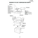
Read Sharp XV-Z12000 (serv.man8) Service Manual online
15
XV-Z12000
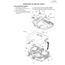
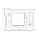
REMOVING OF MAJOR PARTS
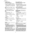
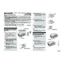
1. Removing the top panels
1-4
B
1-1
2-1
2-2
2-3
1-1
1-1
1-3
1-1
1-4
1-4
1-4
Top body
LED PWB
R/C PWB
Operation PWB
B
A
1-4
1-2
1-1. Remove the six lock screw.
1-2. Press on side Arrow A of the bottom body
1-2. Press on side Arrow A of the bottom body
and Lift the rear body.
1-3. Disconnect the connector.
1-4. Press on front Arrow B of the bottom
1-4. Press on front Arrow B of the bottom
body and unhook the claws, and detach
the top body.
the top body.
2-1. Remove the two screws and detach the LED PWB.
2-2. Remove the one screw and detach the R/C PWB.
2-3. Remove the three screws and detach the operation PWB.
2-2. Remove the one screw and detach the R/C PWB.
2-3. Remove the three screws and detach the operation PWB.
16
XV-Z12000
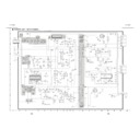
2. Removing the cooling fan and PWB unit assembly.
3-1. Disconnect the ten connectors.
3-2. Remove the two screws and detach the lamp socket.
3-3. Remove the two screws and detach the cooling fan.
3-4. Remove the four screws and detach the PWB unit assembly.
3-2. Remove the two screws and detach the lamp socket.
3-3. Remove the two screws and detach the cooling fan.
3-4. Remove the four screws and detach the PWB unit assembly.
(J5)
(J3)
(RC) (TA)
(J2)
3-1
3-1
3-1
3-3
3-2
Cooling Fan
PWB unit assembly
3-4
3-4
3-4
Door SW
Bi-Metal
LAMP
(FD) (FB)
(FA)
17
XV-Z12000
4-1
4-2
Rear panel
Shield plate
5-1
5-2
5-2
7-1
7-1
8-2
8-2
6-1
PC I/F unit
Main PWB unit
Cooling duct
6-1
(TB)
(EA)
(FC)
(EB)
(CA)
8-3
8-1
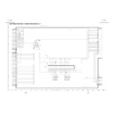
3. Removing the rear panel, PC unit, cooling duct and main PWB unit.
4-1. Remove the two screws.
4-2. Remove the three screws and detach the rear panel.
5-1. Remove the two screws.
5-2. Remove the four hexagonal supports and detach the shield
4-2. Remove the three screws and detach the rear panel.
5-1. Remove the two screws.
5-2. Remove the four hexagonal supports and detach the shield
plate.
6-1. Remove the four screws and detach the PC I/F unit.
7-1. Remove the four screws and detach the cooling duct.
8-1. Remove the two hexagonal supports.
8-2. Remove the five screws and detach the main PWB unit.
8-3. Remove the lock of the holder.
7-1. Remove the four screws and detach the cooling duct.
8-1. Remove the two hexagonal supports.
8-2. Remove the five screws and detach the main PWB unit.
8-3. Remove the lock of the holder.
18
XV-Z12000
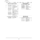
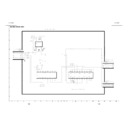
4. Removing the power unit shield , power/ballast unit and power unit.
9.
Remove the seven screws and detach the power unit shield.
10-1. Remove the two screws.
10-2. Remove the four white supports and detach the ballast unit.
11.
10-2. Remove the four white supports and detach the ballast unit.
11.
Remove the four screws and detach the power unit.
11
10-1
10-2
9
Power unit shield
Ballast unit
Power unit
9
11
10-2

