Read Sharp XV-C2E (serv.man3) Service Manual online
XV-C2E
15
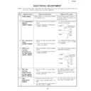
ELECTRICAL ADJUSTMENT
6
VCO
adjustment
(L4101)
adjustment
(L4101)
1. Keep the unit with no signal input.
2. Make connection between TP4101 and
GND.
3. Connect a frequency counter between
TP4102 and TP4101 (GND).
• Turn the core of L4101 to get the
frequency of 15.625±0.01 kHz.
5
PAL free-
running
frequency (2)
for high speed
(R4312, R4420)
running
frequency (2)
for high speed
(R4312, R4420)
1. Receive the PAL monoscope pattern
signal.
2. Connect the dual-beam oscilloscope to
TP4304 and TP4361.
• Turn R4312 and R4420 to obtain
the same waveform as for the
NTSC free-running frequency (2)
adjustment.
NTSC free-running frequency (2)
adjustment.
No.
Adjustment Item
Adjustment Conditions
Adjustment Procedure
1
Initial setting
Before starting the adjustments, initialize
the adjustment data.
the adjustment data.
Press the factory setting "2" button on
the process remote controller to reset
the adjustment data.
the process remote controller to reset
the adjustment data.
4
3
PLL adjustment
(PAL)
(R4339, R4340)
(PAL)
(R4339, R4340)
1. Receive the PAL monoscope pattern
signal.
2. Connect the dual-beam oscilloscope to
TP4305 and TP4306.
• Turn R4339 and R4340 to obtain the
same waveform as for the NTSC
PLL adjustment.
PLL adjustment.
PLL adjustment
(NTSC)
(R4347, R4349)
(NTSC)
(R4347, R4349)
2
1. Receive the NTSC monoscope pattern
signal.
2. Connect a dual-beam oscilloscope to
TP4305 and TP4306.
• Turn R4347 and R4349 to obtain the
waveform shown below.
NTSC free-
running
frequency (2)
for high speed
(R4341, R4343)
running
frequency (2)
for high speed
(R4341, R4343)
1. Receive the NTSC monoscope pattern
signal.
2. Connect the dual-beam oscilloscope to
TP4304 and TP4361.
• Turn R4341 and R4343 to obtain the
waveform shown below.
1
µ
s
GND
GND
2.5V
2.5V
H-SYNC
TP4305
TP4306
Pulse width to
be the same.
be the same.
1
µ
s
GND
GND
2.5V
2.5V
H-SYNC
TP4304
TP4361
Pulse width to
be the same.
be the same.
NOTE: The setting have been factory-adjusted to their best points. If any of them gets out of sprec or after any
relevant part has been replaced, make the related adjustment.
XV-C2E
16
No.
Adjustment Item
Adjustment Conditions
Adjustment Procedure
7
Horizontal
center
adjustment
(NTSC)(DAC)
center
adjustment
(NTSC)(DAC)
1. Receive the NTSC monoscope pattern
signal.
2. Press S2001 to call up the ADJ IN
mode and select the following subject.
Group : VIDEO 1
Subject : H-CENT
• Using the
'
and
"
keys, make the
overscan just the same at right and
left.
left.
8
Horizontal
center
adjustment
(PAL)(DAC)
center
adjustment
(PAL)(DAC)
1. Receive the PAL monoscope pattern
signal.
2. Press S2001 to call up the ADJ IN
mode and select the following subject.
Group :
VIDEO 1
Subject : PAL-H-CENT
• Using the
'
and
"
keys, make the
overscan just the same at right and
left.
left.
9
Contrast (DAC)
(gamma
correction off)
(gamma
correction off)
1. Receive the NTSC 10-step pattern
signal.
2. Connect the dual-beam oscilloscope
between pin (3) of P4201 and GND.
3. Press S2001 to call up the ADJ IN
mode and select the following subject.
Group:
VIDEO 1
Subject: SUB-R, SUB-G, SUB-B
Make sure all these subjects have an
entry of 0 (zero).
entry of 0 (zero).
4. Adjust R861 to get the highest gain.
5. Finally select the following subject.
Group:
VIDEO 1
Subject: CONT
• Using the
'
and
"
keys, adjust the
difference between the 100% white
level and the pedestal level to
1.75±0.05 Vp-p.
level and the pedestal level to
1.75±0.05 Vp-p.
1. Receive the NTSC 10-step pattern
signal.
2. Connect the dual-beam oscilloscope
between pin (5) of P4201 and GND.
3. Put the video mode to the standard
setting.
10
Automatic gain
control (R861)
control (R861)
1. Receive the NTSC 10-step pattern
signal.
2. Connect the dual-beam oscilloscope
between pin (3) of P4201 and GND.
• Turn R861 so that the difference
between the 100% white level and the
pedestal level be 1.35±0.05 Vp-p.
pedestal level be 1.35±0.05 Vp-p.
11
D/A output level
adjustment
adjustment
• Turn R4270 so that the difference
between the 100% white level and the
pedestal level be 0.7±0.05 Vp-p.
pedestal level be 0.7±0.05 Vp-p.
XV-C2E
17
No.
Adjustment Item
Adjustment Conditions
Adjustment Procedure
12
D/A output level
adjustment
(PAL)(DAC)
adjustment
(PAL)(DAC)
1. Receive the PAL 10-step pattern signal.
2. Connect the dual-beam oscilloscope
between pin (5) of P4201 and GND.
3. Select the following subject.
Group : VIDEO 1
Subject : DAVREF
• Using the
'
and
"
keys, adjust the
difference between the 100% white
level and the pedestal level to
0.7±0.05 Vp-p.
level and the pedestal level to
0.7±0.05 Vp-p.
15
Gain
adjustment (1)
(DAC) (standard
video, gamma
correction off)
adjustment (1)
(DAC) (standard
video, gamma
correction off)
1. Receive the NTSC 10-step pattern
signal.
2. Connect the dual-beam oscilloscope
between pin (2) of P4303 and GND.
3. Press S2001 to call up the ADJ IN
mode and select the following subject.
Group :
VIDEO 2
Subject : DRIVE 1
4. Connect the dual-beam oscilloscope
between pin (1) of P4303 and GND.
Subject: R-DRIVE
5. Next connect the dual-beam
oscilloscope between pin (3) of P4303
and GND.
and GND.
Subject: B-DRIVE
• Using the
'
and
"
keys, adjust the
difference between the 100% white
level and the pedestal level to
1.55±0.05 Vp-p.
level and the pedestal level to
1.55±0.05 Vp-p.
(DRIVE1, R-DRIVE, B-DRIVE)
13
Signal center
adjustment
(DAC) (gamma
correction off)
adjustment
(DAC) (gamma
correction off)
1. Receive the NTSC 10-step pattern
signal.
2. Connect the dual-beam oscilloscope
between pin (2) of P4303 and GND.
3. Press S2001 to call up the ADJ IN
mode and select the following subject.
Group : VIDEO 2
Subject : SIG CTR
• Using the
'
and
"
keys, adjust the
center level of the waveform to DC
7.0±0.1 Vp-p.
7.0±0.1 Vp-p.
14
Reference level
adjustment
(DAC) (gamma
correction off)
adjustment
(DAC) (gamma
correction off)
1. Receive the NTSC 10-step pattern
signal.
2. Connect the dual-beam oscilloscope
between pin (2) of P4303 and GND.
3. Press S2001 to call up the ADJ IN
mode and select the following subject.
Group :
VIDEO 2
Subject : SUB-BIAS
4. Connect the dual-beam oscilloscope
between pin (1) of P4303 and GND.
Subject : R-BIAS
5. Next connect the dual-beam
oscilloscope between pin (3) of P4303
and GND.
and GND.
Subject : B-BIAS
• Using the
'
and
"
keys, adjust the
difference between the waveform’s
reference level and the signal center
level to DC 2.0±0.1 Vp-p.
reference level and the signal center
level to DC 2.0±0.1 Vp-p.
(SUB-BIAS, R-BIAS, B-BIAS)
Waveform center level
GND
Waveform center level
XV-C2E
18
No.
Adjustment Item
Adjustment Conditions
Adjustment Procedure
16
Brightness
adjustment
(DAC) (gamma
correction off)
adjustment
(DAC) (gamma
correction off)
Note :
After this
adjustment, go
back to Item 15
"Gain adjustment".
Readjust the gain
level.
adjustment, go
back to Item 15
"Gain adjustment".
Readjust the gain
level.
1. Receive the 10-step pattern signal.
2. Connect the dual-beam oscilloscope
between pin (2) [pin (1) for red, pin (3)
for blue] of P4303 and GND.
for blue] of P4303 and GND.
3. Press S2001 to call up the ADJ IN
mode and select the following subject.
Group : VIDEO 1
Subject : BRIGHT(G), R-BRT, B-BRT
• Using the
'
and
"
keys, adjust the
difference between the 100% white
level and the pedestal level to
5.9±0.1 Vp-p.
level and the pedestal level to
5.9±0.1 Vp-p.
17
Gamma
adjustment
(DAC) (gamma
correction off)
adjustment
(DAC) (gamma
correction off)
1. Receive the NTSC 10-step pattern
signal.
2. Connect the dual-beam oscilloscope
between pin (2) of P4303 and GND.
3. Press S2001 to call up the ADJ IN
mode and select the following subject.
Group : VIDEO 4
Subject : RGB GAM1, RGB CTR1
4. Connect the dual-beam oscilloscope
between pin (1) of P4303 and GND.
5. Press S2001 to call up the ADJ IN
mode and select the following subject.
Group : VIDEO 4
Subject : R GAM1, R CTR1
6. Connect the dual-beam oscilloscope
between pin (1) of P4303 and GND.
7. Press S2001 to call up the ADJ IN
mode and select the following subject.
Group : VIDEO 4
Subject : B GAM1, B CTR1
• Using the
'
and
"
keys, adjust the
second-tone level to 4.2±0.1 Vp-p
and the black level to 3.0±0.1 Vp-p.
and the black level to 3.0±0.1 Vp-p.
18
SID signal level
adjustment
adjustment
1. Receive the NTSC 10-step pattern
signal.
2. Connect the dual-beam oscilloscope
between pin (6) of P4303 and GND.
3. Press S2001 to call up the ADJ IN
mode and select the following subject.
Group:
VIDEO 3
Subject: SID CTR
• Using the
'
and
"
keys, adjust the
waveform’s top and bottom levels
from its center level to 4.0±0.1 Vp-p.
from its center level to 4.0±0.1 Vp-p.
GND
GND
Black level
Second-tone level
4.0V
4.0V

