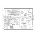
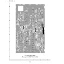
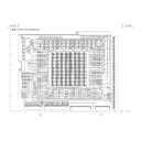
Read Sharp XG-V10XE (serv.man9) Service Manual online
20
XG-V10XE
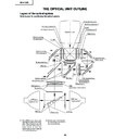
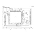
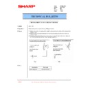
THE OPTICAL UNIT OUTLINE
Layout of the optical system
Note: Layout for positioning the optical system.
★
M2 and M3 mirrors have a coat-
ing wedge (for different film thick-
ness). Set up these mirrors, with
their markings positioned as
shown above, so that their
coated faces and both sides be
in the correct directions.
ing wedge (for different film thick-
ness). Set up these mirrors, with
their markings positioned as
shown above, so that their
coated faces and both sides be
in the correct directions.
L1
★
2 Output polarizer R
★
2 Output polarizer G
Projection Lens
R-LCD
Dichroic coating
(R transmission)
Dichroic coating
(G transmission)
M5
AL-coated mirror R
AL-deposited face
Marking
L2(R)
★
M2
G-LCD
Marking
L2(G)
M4
M6
B/G reflector
Dichroic coating
UV absorbing glass
PBS aperture
Fly-eye lens
UHP lamp
(Light source)
Marking
Prism array
UV-IR filter
UHP lamp
(Light source)
PBS
(polarization beam splitter)
Relay lens 1
(B transmission)
Dicroic coating
AL-deposited face
Relay lens 2
AL-coated mirror B
AL-coated mirror B
★
M3
L1
G01
G/R Reflector
Marking
B-DF
G02
G03
AL-deposited face
Relay lens 3
Input polarizer B
B-LCD
★
2 Output polarizer B
Cross dichroic prism
RED
GREEN
BLUE
★
2 See the assemble-illustration
for determing a direction of
the output polarizer.
the output polarizer.
21
XG-V10XE
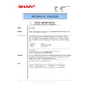
CONVERGENCE AND FOCUS ADJUSTMENT
»
Place the set in the ceiling-mounted position, open the maintenance door, and start the
convergence and focus adjustments. Make sure the settings are complete and then turn
on the power. For adjusting the image, use the remote controller. Take the following
adjustment procedures.
convergence and focus adjustments. Make sure the settings are complete and then turn
on the power. For adjusting the image, use the remote controller. Take the following
adjustment procedures.
1. Focusing the projection lens
(A) Replacing all the 3 LCD panels
1. Before replacing all the 3 LCD panels, project an image on the screen and bring it into focus.
2. Replace the panels with new ones. But until the focus has been completely readjusted, be careful not to
2. Replace the panels with new ones. But until the focus has been completely readjusted, be careful not to
change the distance between the set and the screen, nor to move the projection lens focus and zoom
rings.
If the focus is readjusted with a different positional relation, the relation between the projection distance
and the screen size is affected. In other words, a short-distance image (40 WIDE, for example) may get
out of the focus range, or a long-distance image (300 WIDE, for example) may come out of focus.
(B) Replacing 1 or 2 of the 3 LCD panels
1. In adjusting the focus after replacement of one or two LCD panels, project an image on the screen and turn
the projection lens focus ring to get the non-replaced LCD panel into focus.
2. But until the focus has been completely adjusted for the new LCD panels, be careful not to change the
distance between the set and the screen, nor to move the projection lens focus and zoom rings.
(If the distance has been changed or the projection lens readjusted, repeat the above steps 1 and 2.)
(If the distance has been changed or the projection lens readjusted, repeat the above steps 1 and 2.)
2. Adjusting the G-LCD panel
(A) Focus adjustment. (Make this adjustment on the white-only screen.)
1. Right-and-left focus adjustment (
θ
Y direction) .
Loosen the lock screws "b" and "c" and insert the eccentric screwdriver into the notch and hole "b". Turn
the screwdriver until the right and left halves on the screen get into focus.
First get the right and left halves in balance. Then improve the accuracy while making the adjustment 2
below.
the screwdriver until the right and left halves on the screen get into focus.
First get the right and left halves in balance. Then improve the accuracy while making the adjustment 2
below.
2. Top-center-bottom focus adjustment (
θ
X and Z directions).
Loosen the lock screws "a" and "c" and insert the eccentric screwdriver into the notch and hole "a" or "c".
Turn the screwdriver until the top, center and bottom on the screen get into focus. In adjusting this top-to-
bottom focus, temporarily tighten the lock screw "b" to fix the
Turn the screwdriver until the top, center and bottom on the screen get into focus. In adjusting this top-to-
bottom focus, temporarily tighten the lock screw "b" to fix the
θ
Y direction adjustment.
3. Repeat the above steps 1 and 2 to finely adjust the focus. Finally tighten up all the lock screws.
Notes :
1
Carefully proceed with the focus adjustment because the adjusting directions are correlated.
2
In adjusting the convergence and focus, do not move the projection lens zoom and focus rings until the end
of all the adjustments.
of all the adjustments.
(B) Convergence adjustment
»
The G-LCD panel has no convergence adjustment mechanism. Use this panel as convergence adjustment
reference.
reference.
3. B-LCD panel adjustment (the same for the R-LCD panel)
(A) Focus adjustment
»
Take the same procedure as for the G-LCD panel focus adjustment. Note that the adjustment range is small
in the Z direction. If the convergence is quite different between the B-LCD and G-LCD panels, roughly adjust
the convergence first and then the focus.
in the Z direction. If the convergence is quite different between the B-LCD and G-LCD panels, roughly adjust
the convergence first and then the focus.
(B) Convergence adjustment
»
Use a crosshatch pattern signal for this adjustment.
Make the adjustment just for the G-color and the relevant color.
(1) Loosen the convergence lock screw "d".
(2) With the G-LCD panel’s screen center as reference, adjust the B-LCD panel in the X, Y and
Make the adjustment just for the G-color and the relevant color.
(1) Loosen the convergence lock screw "d".
(2) With the G-LCD panel’s screen center as reference, adjust the B-LCD panel in the X, Y and
θ
Z directions.
(3) Finally tighten up the convergence lock screw "d".
22
XG-V10XE
Convergence and Focus Adjustments Mechanism
Notes :
1
The eccentric cam is used for convergence adjustment. This means that the cam’s turning and the linear
movement are not always uniform.
movement are not always uniform.
2
This model is not equipped with the LCD image adjustment mechanism. This is because the dichroic prism
is used for image formation. When the LCD panels all get into the best focus, the images are almost
completely converged.
is used for image formation. When the LCD panels all get into the best focus, the images are almost
completely converged.
R-LCD
G-LCD
Notch and hole "c"
G adjusting plate
G-LCD
Eccentric cam
Lock screw "c"
Notch and hole "b"
Lock screw "b"
Lock screw "b"
Notch and hole "c"
Lock screw "c"
X
Z
θ
Y
θ
X
Y
Z
θ
Y
Z
X
B-LCD
Notch and hole "a"
Lock screw "a"
FRONT
Lock screw "d"
(convergence
adjustment)
RáB-LCD panel
mounting screws
RáB-LCD
θ
Z
Y
X
G-LCD panel
mounting screws
BOTTOM VIEW
SIDE VIEW
SIDE VIEW (from outside)
SIDE VIEW (from inside)
TOP
TOP
23
XG-V10XE
X direction
LCD right and left
Convergence Y direction
LCD top and bottom
θ
Z direction
Rotation around Z axis
LCD turning axis
Z direction
LCD optical axis
Focus
θ
X direction
Rotation around X axis
LCD top-to-bottom flapping
θ
Y direction
Rotation around Y axis
LCD right-to-left flapping
X direction
±
0.8mm Eccentric cam
Eccentric cam adjusting wrench
d
Hex wrench
Convergence
Y direction
±
0.8mm Eccentric cam
Eccentric cam adjusting wrench
d
Hex wrench
R/B
θ
Z direction
±
1
°
Eccentric cam
Eccentric cam adjusting wrench
d
Hex wrench
colors
Z direction
±
1.3mm Notch and hole "a" & "c"
Eccentric screwdriver
a, c
Focus
θ
X direction
±
1
°
Notch and hole "a" & "c"
a, c
θ
Y direction
±
2.5
°
Notch and hole "b" & "c"
b, c
Z direction
±
0.4mm
G color
Focus
θ
X direction
±
1
°
Same as for R and B colors
θ
Y direction
±
2.5
°
Color
Adjustment
Direction
Movement
Position
Adjusting tool
Lock screw
Tightening tool
Convergence and Focus Adjustments at a Glance
Adjustment directions
Adjustment
Direction
Definition
Direction of LCD panel
Convergence and Focus Adjustment for the Optical Mechanism
Phillips
screwdriver,
*Hex wrench
screwdriver,
*Hex wrench
Focus Adjustments the Other Way
a
Notch and hole "a"
Z and
θ
X directions
b
Notch and hole "b"
θ
Y direction
c
Notch and hole "c"
Z,
θ
X and
θ
Y directions
Lock screw
Position
Related direction
Tool
Specific or General
Tool code
Configuration
Eccentric cam
Specific
9DASPN-XGNV1U
adjusting wrench
Eccentric screwdriver Specific
9EQDRiVER-NV1A
Hex wrench
General (redesigned)
9EQLNC-XGNV1U
2
5
16
R2
50
CUT
Convergence and Focus Adjusting and Tightening Tools
*Hex wrench
General
—
Preferably use a 70 mm or longer
screwdriver (with a handle).
screwdriver (with a handle).
Phillips screwdriver
General
—
For M2.6 pan-head machine screw
100
80

