Read Sharp XG-NV5XE (serv.man46) Service Manual online
10
XG-NV5XE
XG-NV5XM
XG-NV5XM
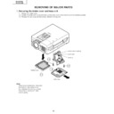
REMOVING OF MAJOR PARTS
1. Removing the Intake cover and lamp unit
1-1. Detach the Intake cover.
1-2. Loosen the lamp cover screw and draw out the lamp cover in the direction of arrow (toward yourself).
1-3. Remove the two lamp unit lock screws. Detach the lamp unit.
1-2. Loosen the lamp cover screw and draw out the lamp cover in the direction of arrow (toward yourself).
1-3. Remove the two lamp unit lock screws. Detach the lamp unit.
Note:
When replacing the lamp, make sure
that there is a clearance of over
8mm between the terminal and the
lamp snap-on spring (and other
metallic parts).
that there is a clearance of over
8mm between the terminal and the
lamp snap-on spring (and other
metallic parts).
SHARP
1-3
1-3
1-2
1-1
Lamp snap-on spring
Lamp unit
Terminal
Intake cover
Lamp cover
11
XG-NV5XE
XG-NV5XM
XG-NV5XM
2. Removing the top and rear cabinets
2-1. Remove the five rear cabinet lock screws.
2-2. Remove the four terminal board lock screws off the rear cabinet. Unhook and detach the rear cabinet from
2-2. Remove the four terminal board lock screws off the rear cabinet. Unhook and detach the rear cabinet from
below.
2-3. Remove the four top cabinet lock screws from below.
2-4. Slowly lift the top cabinet and disconnect the operation key unit connector (KY). Then take away the top
cabinet.
SHARP
2-4
(KY)
Top Cabinet
Rear cabinet
Video Unit (for XG-NV5XM
as well as AUSTRALIA,
NEW ZEALAND and HONG KONG
versions of XG-NV5XE)
as well as AUSTRALIA,
NEW ZEALAND and HONG KONG
versions of XG-NV5XE)
SHARP
2-3
2-2
2-1
Press both sides of the bottom
cabinet in the directions of
arrow to undo the hooks. Lift
and detach the top cabinet.
cabinet in the directions of
arrow to undo the hooks. Lift
and detach the top cabinet.
Hook
12
XG-NV5XE
XG-NV5XM
XG-NV5XM
3. Removing the PWB units
3-1. Disconnect the connectors.
3-2. Remove the twelve screws and detach the output Unit top shield.
3-3. Remove the two screws and detach the PC I/F Unit.
3-4. Remove the two screws and the spacer (stud bolt).Lift and detach the Unit assembly.
3-5. Remove the S-out/REG unit angle lock screw and take out the S-out/REG unit.
3-2. Remove the twelve screws and detach the output Unit top shield.
3-3. Remove the two screws and detach the PC I/F Unit.
3-4. Remove the two screws and the spacer (stud bolt).Lift and detach the Unit assembly.
3-5. Remove the S-out/REG unit angle lock screw and take out the S-out/REG unit.
3-1
3-5
(FP)
(FS)
(Q)
(FN)
(EB)
(EB)
(SO)
(SP)
(EA)
(F)
(SO)
3-1
(L)
3-3
3-2
3-4
3-4
3-4
(EB)
PC Terminal Unit
Signal Unit
PC I/F Unit
Spacer (stud bolt)
Output Unit
Output Unit top shield
S-out/REG Unit Angle
S-out/REG Unit
Video Unit (for XG-NV5XM
as well as AUSTRALIA,
NEW ZEALAND and
HONG KONG versions of
XG-NV5XE)
as well as AUSTRALIA,
NEW ZEALAND and
HONG KONG versions of
XG-NV5XE)
13
XG-NV5XE
XG-NV5XM
XG-NV5XM
4. Removing the Power/Ballast unit assembly
4-1. Remove the Power/Ballast unit assembly lock screw.
4-2. Remove the two lamp socket holder lock screws and take out the holder.
4-3. Disconnect the connector (BA) from the ballast unit.
4-4. Remove the (FG) lead lock screw.
4-5. Lift the Power/Ballast unit assembly off the position.
4-2. Remove the two lamp socket holder lock screws and take out the holder.
4-3. Disconnect the connector (BA) from the ballast unit.
4-4. Remove the (FG) lead lock screw.
4-5. Lift the Power/Ballast unit assembly off the position.
4-4
(BA)
4-1
4-2
4-3
4-5
(FG)
Power/Ballast Unit Ass'y

