Read Sharp XG-C455W (serv.man7) Service Manual online
XG-C455W/PG-C355W
3 – 1
XG-C455W
Service Manual
CHAPTER 3.
THE OPTICAL UNIT OUTLINE
[1] THE OPTICAL UNIT OUTLINE
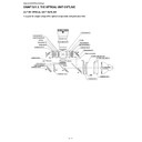
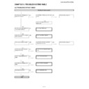
1. Layout for proper setup of the optical components and parts (top view)
Output polarizer R
Output Pre-polarizer R
LCD (R)
Input polarizer R
Dichroic filter R
Condenser lens R
Projection Lens
Cross dichroic
prism
M3
R
re
flect
or
CL4
CL5
Condenser lens 5
Input polarizer G
Input Pre-polarizer G
Condenser lens G
M3
M2
CL4
R
re
flec
tor
Condenser lens 4
M1
LCD (G)
CL3-G
B
refl
ec
tor
G
ref
le
cto
r
CL3
CL1
CL2
PBS
Condenser lens 2
Condenser lens 1
Light source
(Lamp)
(Lamp)
Input polarizer B
Output compensator
Output polarizer B
Output polarizer G
Input pre-polarizer B
LCD (B)
Condenser lens B
FLYEYE LENS (OUTPUT)
FLYEYE LENS (INPUT)
B
reflect
or
M4
XG-C455W/PG-C355W
3 – 2
2. Adjusting the mirrors
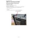
This adjustment is needed when any of the optical parts of the optical mechanism has been replaced.
1. Disconnect the flat cables from all the LCD panels.
2. Light up the lamp.
3. Project a white-light image and check to see if there is any color tint in any direction. If any, use the M2, M4 and M5
adjusting levers.
4. Loosen the adjusting lever lock screws, make adjustments, and tighten up the lock screws.
B l a c k
B l a c k
B l a c k
XG-C455W/PG-C355W
3 – 3
3. Replacing the prism holder unit
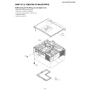
1. Remove the 2 lock screws, and take the prism holder unit out of the optical unit.
2. Replace the prism holder unit with new one. Take the above step 1 in reverse order.
NOTE: Even if just one of the LCD panels is defective, it is necessary to replace the entire prism unit. Do not replace
just the defective LCD panel only. Under the present circumstances, please do not touch the display part of
LCD.
G-LCD panel
Optical unit
R-LCD panel
Prism holder unit lock screws
B-LCD panel
XG-C455W/PG-C355W
3 – 4
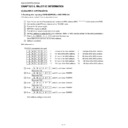
4. How to replace LCD panel
• As high precision is required for assembling the prism folder unit, it should be done only in the case where any appropriate, exclusive equipment
Stage ( 5µm adjustment precision)) is available. If no such equipment is available, it is requested to replace
the prism folder unit .
• The three LCD panels in the prism folder unit are combined by adjusting the difference in their characteristics when producing at the factory. If any
of the panels is replaced, more or less discoloration may occur while a dark screen is projected (see the Fig. below).
1. Remove four screws.
2. Replace the LCD.
3. Tighten the screw with 0.15±0.03N
•m.
4. Dissolve the UV adhesive once, and bond the LCD panel again after matching its position.
adjuster with resolution of approx. 5
µm) are necessary. If you do not have them, replace the prism holder unit as described in the Ser-
Stage ( 5
µm adjustment precision).
• The three LCD panels are produced adjusting the difference in characteristics. If only one LCD panel is replaced, irregular color may
occur at the corner part when projecting the whole black scene.
Partial discoloration appearing
at diagonal corner sections
at diagonal corner sections
4 places
(KZGFYKVJ78CFJGUKXG
(KZGFYKVJ78CFJGUKXG
RNCEGU
(KZGFYKVJ.%&UETGY
(KZGFYKVJ.%&UETGY

