Read Sharp PG-M25XE (serv.man7) Service Manual online
13
PG-M25X
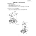
REMOVING OF MAJOR PARTS
1. Removing the top panel
1-1. Detach the terminal block cover.
1-2. Remove the five lock screws from the top panel.
1-3. Press the right side of the bottom body to undo the hook.
1-4. Press the left side of the bottom body to undo the hook.
1-5. Press the front of the bottom body to undo the hook. Get the top panel loose from the bottom body.
1-6. Slightly raise the front of the top panel and disconnect the speaker connector.
2. Removing the PC I/F PWB and cooling fan
2-1. Disconnect the connector.
2-2. Remove the three lock screws from the PC I/F PWB and then the two hex support screws.
2-3. Disconnect the connector and take out the cooling fan.
2-2. Remove the three lock screws from the PC I/F PWB and then the two hex support screws.
2-3. Disconnect the connector and take out the cooling fan.
Top panel
Terminal block cover
1-2
1-1
1-2
1-2
1-2
1-6
1-2
1-5
1-4
1-3
2-2
2-1
PC I/F PWB unit
2-3
2-3
Cooling fan
2-2
14
PG-M25X
3. Removing the operation PWB
3-1. Remove the two lock screws from the operation PWB and slightly raise this PWB.
3-2. Disconnect the connectors.
3-2. Disconnect the connectors.
4. Removing the optical mechanism
4-1. Remove the two lock screws from the lamp socket.
4-2. Raise the two lamp socket lead fixtures.
4-3. Disconnect the connectors.
4-4. Remove the six lock screws from the optical mechanism.
4-2. Raise the two lamp socket lead fixtures.
4-3. Disconnect the connectors.
4-4. Remove the six lock screws from the optical mechanism.
3-2
3-1
3-1
Operation PWB unit
4-4
4-3
4-1
Optical mechanism
4-2
15
PG-M25X
5. Removing the other PWBs
5-1. Disconnect the connectors.
5-2. Remove the four lock screws from the power PWB.
5-2. Remove the lock screw from the ballast PWB unit.
5-2. Remove the three hex support screws from the input PWB.
5-2. Remove the lock screw from the terminal block cover.
5-2. Remove the three lock screws from the PFC PWB.
5-2. Remove the four lock screws from the power PWB.
5-2. Remove the lock screw from the ballast PWB unit.
5-2. Remove the three hex support screws from the input PWB.
5-2. Remove the lock screw from the terminal block cover.
5-2. Remove the three lock screws from the PFC PWB.
6. Removing the formatter PWB
6-1. Disconnect the connector.
6-1. Remove the two lock screws from the heat sink.
6-1. Remove the four lock screws from the backer plate assembly, and detach the formatter PWB.
Note: The DMD (Digital Micromirror Device) unit is easily affected by static electricity. In handling this unit, be sure
to wear a wristband or take other anti-static measure.
5-3
Bottom body
Ballast PWB unit
5-6
5-2
5-1
5-1
5-1
PFC PWB unit
Power PWB unit
Input PWB unit
5-4
5-5
6-2
6-1
6-3
Formatter PWB unit
Backer plate assembly
DMD (Digital Micromirror
Device) unit
Device) unit
Heat sink
16
PG-M25X
* Precautions in setting up the DMD (Digital Micromirror Device) unit
Before connecting the formatter PWB to the optical engine, take the following steps. Look at the voltage rank marking
that is on the DMD itself. Referring to this marking, set the DIP switches on the formatter PWB. And connect this PWB
* Connecting the FPC extension cables (QCNW-A298WJZZ)
Connect the cables to the formatter PWB (TO FMT) and the PC I/F PWB (TO PC), referring to the silk-screen-printed
markings. See the sketch below. (The FPC is already connected at TO PC.)
Voltage rank marking
This sample is "C".
This sample is "C".
B
C
D
E
TO PC
TO FMT

