Read Sharp PG-M25XE (serv.man5) Service Manual online
8
PG-M25X
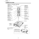
Location of Controls
Projector (Front and Top View)
Foot releases/Adjustment
feet
feet
For adjusting the projector’s
height.
height.
Attaching the terminal cover
Attach the terminal cover by
placing it on the side panel of the
projector and pressing it into
place, as shown in the illustration.
TEMPERATURE
warning indicator
warning indicator
Illuminates in green
normally. When the
internal temperature
rises, this indicator will
illuminate in red.
normally. When the
internal temperature
rises, this indicator will
illuminate in red.
Zoom knob
Focus ring
AV MUTE button
For temporarily turning off the
sound and picture.
sound and picture.
ENTER button
For setting items selected or
adjusted on the menu.
adjusted on the menu.
Adjustment buttons
(
(
"'\ |
For selecting menu items.
LENS button
For adjusting Keystone or
Digital Shift setting.
Digital Shift setting.
POWER button
Turns the power on or off.
POWER indicator
Illuminates in red, when the
projector is in standby. When
the power is turned on, this
indicator will illuminate in
green.
projector is in standby. When
the power is turned on, this
indicator will illuminate in
green.
LAMP replacement
indicator
indicator
Illuminates in green normally.
Replace the lamp when the
indicator illuminates in red.
Replace the lamp when the
indicator illuminates in red.
AUTO SYNC button
For automatically
adjusting images when
connected to a computer.
adjusting images when
connected to a computer.
UNDO button
For undoing an operation
or returning to the default
settings.
or returning to the default
settings.
VOLUME buttons
For adjusting the speaker
sound level.
sound level.
MENU button
For displaying adjustment
and setting screens.
and setting screens.
INPUT button
For switching input mode
1, 2, 3 or 4.
1, 2, 3 or 4.
Remote control
sensor
sensor
Terminal cover
Speaker
GyroRemote
Antenna
)
9
PG-M25X
Projector (Side View)
Exhaust vent
AC socket
Kensington Security
Standard connector
Standard connector
Using the Kensington Lock
This projector has a Kensington Security Standard connector for use with a Kensington MicroSaver Security
System. Refer to the information that came with the system for instructions on how to use it to secure the
projector.
System. Refer to the information that came with the system for instructions on how to use it to secure the
projector.
Attaching the lens cap
After putting the lens cap strap on the lens cap, pass
the other end of the strap through the hole under the
projector, next to the lens, as shown in the illustration.
After putting the lens cap strap on the lens cap, pass
the other end of the strap through the hole under the
projector, next to the lens, as shown in the illustration.
Bottom View
INPUT 2 terminal
Terminal for connecting video
equipment with an S-VIDEO
terminal.
equipment with an S-VIDEO
terminal.
INPUT 1 terminal
Port for DVI digital, computer
RGB, and COMPONENT
signals.
RGB, and COMPONENT
signals.
INPUT 3 terminal
For connecting video
equipment.
equipment.
INPUT AUDIO terminal
Shared audio terminal for
INPUT 1, INPUT 2,
INPUT 3 and INPUT 4.
INPUT 1, INPUT 2,
INPUT 3 and INPUT 4.
USB terminal
For connecting a computer
using a USB cable.
using a USB cable.
Wired remote contorl
input terminal (ø3.5 mm
minijack)
input terminal (ø3.5 mm
minijack)
INPUT 4 terminal
For inserting a wireless
LAN PC card or a memory
card.
LAN PC card or a memory
card.
10
PG-M25X
GyroRemote
Gyration U.S. Patents
5698784, 5825350, 5898421
5698784, 5825350, 5898421
WIRE R/C JACK
Bottom
Front
Rear
Function 1 / 2 buttons
For specifying the button assignments
for Function 1 and Function 2
for Function 1 and Function 2
INPUT button
For switching between inputs 1,2,3
and 4.
and 4.
L-CLICK/ ENTER button
For entering menu items or to perform
a left click when using the
wireless mouse.
a left click when using the
wireless mouse.
POWER button
For turning the power on or off.
LENS button
For adjusting Keystone or Digital Shift
setting.
setting.
Function 3 / 4 buttons
For specifying the button assignments
for Function 3 and Function 4
for Function 3 and Function 4
LED indicator
Lights up when the GyroRemote is in
motion.
motion.
POINTER button
Holding this button down displays a
pointer on the screen.
pointer on the screen.
R-CLICK / UNDO button
For undoing an operation or to
perform a right click when using the
wireless mouse.
perform a right click when using the
wireless mouse.
MENU button
For displaying adjustment and
setting screens.
setting screens.
VOLUME buttons
For adjusting the speaker sound
level.
level.
ASSIGN button
Switches the button assignment
function group.
function group.
RF CH+ button
For checking the current RF channel
as well as switching the channel.
as well as switching the channel.
GYRO ACTIVE
For moving the Gyro
function for actions such
as moving tool icons
(such as stamp), selecting
menus in the OSD, or
moving the cursor using
the wireless mouse.
function for actions such
as moving tool icons
(such as stamp), selecting
menus in the OSD, or
moving the cursor using
the wireless mouse.
Wired remote
terminal
(ø2.5 mm
minijack)
terminal
(ø2.5 mm
minijack)
TEACH (OK) button
For registering the GyroRemote in the
projector.
projector.
11
PG-M25X
Connection Pin Assignments
17
• • • • • • • • •
~
• • • • • • • • •
• • • •
~
• • • •
• • • •
~
• • • •
24
18
23
C3
2
1
9
16
C1
C2
C4
C2
C4
C5
8
7
•
DVI Digital INPUT
Pin No.
Signal
Pin No.
Signal
1
T.M.D.S data 2–
16
Hot plug detection
2
T.M.D.S data 2+
17
T.M.D.S data 0–
3
T.M.D.S data 2 shield
18
T.M.D.S data 0+
4
Not connected
19
T.M.D.S data 0 shield
5
Not connected
20
Not connected
6
DDC clock
21
Not connected
7
DDC data
22
T.M.D.S clock shield
8
Not connected
23
T.M.D.S clock+
9
T.M.D.S data 1–
24
T.M.D.S clock–
10
T.M.D.S data 1+
C1
Not connected
11
T.M.D.S data 1 shield
C2
Not connected
12
Not connected
C3
Not connected
13
Not connected
C4
Not connected
14
+5V current
C5
Ground
15
Ground
DVI Digital / Analog INPUT 1 port : 29 pin connector
•
DVI Analog RGB Input
Pin No.
Signal
Pin No.
Signal
1
Not connected
16
Hot plug detection
2
Not connected
17
Not connected
3
Not connected
18
Not connected
4
Not connected
19
Not connected
5
Not connected
20
Not connected
6
DDC clock
21
Not connected
7
DDC data
22
Not connected
8
Vertical sync
23
Not connected
9
Not connected
24
Not connected
10
Not connected
C1
Analog input Red
11
Not connected
C2
Analog input Green
12
Not connected
C3
Analog input Blue
13
Not connected
C4
Horizontal sync
14
+5V current
C5
Ground
15
Ground
•
DVI Analog Component Input
Pin No.
Signal
Pin No.
Signal
1
Not connected
16
Not connected
2
Not connected
17
Not connected
3
Not connected
18
Not connected
4
Not connected
19
Not connected
5
Not connected
20
Not connected
6
Not connected
21
Not connected
7
Not connected
22
Not connected
8
Not connected
23
Not connected
9
Not connected
24
Not connected
10
Not connected
C1
Analog input Pr/Cr
11
Not connected
C2
Analog input Y
12
Not connected
C3
Analog input Pb/Cb
13
Not connected
C4
Not connected
14
Not connected
C5
Ground
15
Ground
1
2
4
3
4-pin USB connector
•
USB connector: 4 pin B-type USB connector
Pin no.
Signal
Name
1
VCC
USB current
2
USB–
USB data–
3
USB+
USB data+
4
SG
Signal Ground

