Read Sharp PG-M25XE (serv.man10) Service Manual online
21
PG-M25X
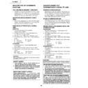
ELECTRICAL ADJUSTMENT
1
Initialization of
EEPROM
EEPROM
1. Turn on the power (the lamp lights
up) and warm up the system for 15
minutes.
minutes.
No.
Adjustment Items
Adjustment Conditions
Adjustment Procedures
1. Carry out the following setting.
Press SW2001 to enter the process
mode, and execute S2 on SSS menu.
mode, and execute S2 on SSS menu.
2
Adjustment of CW
index
index
1. Signal input: 64-step color bar
2. Select the following group and sub-
2. Select the following group and sub-
ject.
Group: DLP
Subject: Select CW-INDEX.
Group: DLP
Subject: Select CW-INDEX.
1. Feed the signal to INPUT 1.
2. Select subject and make adjustment
2. Select subject and make adjustment
so that the lamp gradation patterns
of R, G and B should be smooth with-
out noise.
of R, G and B should be smooth with-
out noise.
R
G
B
3
Adjustment of
RGB gradation
reproduction
RGB gradation
reproduction
1. Feed the SMPTE pattern signal.
2. Select the following group and sub-
2. Select the following group and sub-
ject.
Group: DLP
Subject: G1-GAIN
Group: DLP
Subject: G1-GAIN
1. Confirm that 100% and 95% white
gradation, and 0% and 5% black gra-
dation are discernible.
dation are discernible.
2. If the white gradation looks differently,
do fine adjustment by G1-GAIN.
4
Adjustment of
video brightness/
contrast
video brightness/
contrast
1. Feed the NTSC100% window pat-
ter signal. (Burst signal)
2. Select the following group and sub-
ject.
Group: VIDEO
Subject: AUTO
Group: VIDEO
Subject: AUTO
1. After signal input, select AUTO us-
ing the set's switch or the remote
controller's button for automatic ad-
justment.
controller's button for automatic ad-
justment.
5
Adjustment of
video tint
video tint
1. Feed the split color bar signal.
2. Select the following group and sub-
2. Select the following group and sub-
ject.
Group: VIDEO
Subject: TINT
Group: VIDEO
Subject: TINT
1. Confirm the fixed value.
Fixed value: 128
22
PG-M25X
6
Adjustment of
NTSC color
saturation
NTSC color
saturation
1. Feed the internal 8ch (split color bar)
signal.
2. Select the following group and sub-
ject.
Group: VIDEO
Subject: N-COLOR
Group: VIDEO
Subject: N-COLOR
No.
Adjustment Items
Adjustment Conditions
Adjustment Procedures
1. Confirm the fixed value.
Fixed value: 59
7
Adjustment of PAL
color saturation
color saturation
1. Feed the PAL color bar signal.
2. Select the following group and sub-
2. Select the following group and sub-
ject.
Group: VIDEO
Subject: P-COLOR
Group: VIDEO
Subject: P-COLOR
1. Confirm the fixed value.
Fixed value: 59
8
Adjustment of
SECAM color
saturation
SECAM color
saturation
1. Feed the SECAM color bar signal.
2. Select the following group and sub-
2. Select the following group and sub-
ject.
Group: VIDEO
Subject: S-COLOR
Group: VIDEO
Subject: S-COLOR
1. Confirm the fixed value.
Fixed value: 59
9
Adjustment of
COMPO G bright-
ness
COMPO G bright-
ness
1. Input signal: 0% gray pattern sig-
nal (480I)
2. Select the following group and sub-
ject.
Group: COMPO
Subject: G-BRIGHT
Group: COMPO
Subject: G-BRIGHT
1. Feed the signal to INPUT 1.
Make adjustment so that some bits
should be missing in the picture.
should be missing in the picture.
10
Adjustment of
COMP CR-Offset
COMP CR-Offset
1. Feed the color difference signal
(480I): Y 0% brightness, Cb and Cr
0% white patterns.
Group: COMPO
Subject: AUTO
0% white patterns.
Group: COMPO
Subject: AUTO
1. After signal input, select AUTO us-
ing the set's switch or the remote
controller's button for automatic ad-
justment.
controller's button for automatic ad-
justment.
11
Automatic Adjust-
ment of RGB
white balance
ment of RGB
white balance
1. Feed the 50% gray pattern signal
(XGA, 60 Hz).
2. Select the following group and sub-
ject.
Group: DLP
Subjects: R1-GAIN (Red)
Group: DLP
Subjects: R1-GAIN (Red)
B1-GAIN (Blue)
1. Adjust R-1 GAIN and B1-GAIN so that
x-value should be 266±3 and y-value
320±3.
320±3.
12
Automatic Adjust-
ment of SRGB
white balance
ment of SRGB
white balance
1. Feed the 50% gray pattern signal
(XGA, 60 Hz).
2. Select the following group and sub-
ject.
Group: DLP
Subjects: S-R1-GAIN (Red)
Group: DLP
Subjects: S-R1-GAIN (Red)
S-G1-GAIN (Green)
S-B1-GAIN (Blue)
S-B1-GAIN (Blue)
1. Set the value of S-R1-GAIN to 34.
2. Adjust S-G1-GAIN and S-B1-GAIN
2. Adjust S-G1-GAIN and S-B1-GAIN
so that x-value should be 310±3 and
y-value 335±3.
y-value 335±3.
23
PG-M25X
13
Automatic adjust-
ment of video
white balance
ment of video
white balance
1. Feed the 50% gray pattern signal
(NTSC, burst signal).
2. Select the following group and sub-
ject.
Group: DLP
Subjects: V-R1-GAIN (Red)
Group: DLP
Subjects: V-R1-GAIN (Red)
V-B1-GAIN (Blue)
No.
Adjustment Items
Adjustment Conditions
Adjustment Procedures
1. Adjust V-R1-GAIN and V-B1-GAIN so
that x-value should be 265±3 and y-
value should be 298±3.
value should be 298±3.
14
Automatic adjust-
ment of DTV white
balance
ment of DTV white
balance
1. Feed the 50% gray pattern signal
(480I, color difference signal).
2. Select the following group and sub-
ject.
Group: DLP
Subjects: C-R1-GAIN
Group: DLP
Subjects: C-R1-GAIN
C-B1-GAIN
1. Adjust C-R1-GAIN and C-B1-GAIN
so that x-value should be 263±3 and
y-value should be 295±3.
y-value should be 295±3.
15
Adjustment of
DLP voltage (For
reference)
DLP voltage (For
reference)
1. Read voltage rank of DLP descrip-
tion.
2. Set the switch corresponding to the
rank which has been read. (on the
formatter PWB)
formatter PWB)
1. Carry out adjustment when DLP chip
has been replaced or combination of
chip and formatter has been changed.
chip and formatter has been changed.
2. Rank:
B C D E
Setting value: 1 2 3 4
16
Frequency adjust-
ment
ment
1. Turn on the Gyro remote control unit
power.
2. Adjust the frequency at TP5801 to
12800000±40 Hz.
1. Be sure to keep only the Gyro re-
mote control unit on power.
2. Ta ke t h e f r e q u e n c y r e a d i n g a t
TP5801 and readjust the trimmer
capacitor (C5835), as required, to the
specified frequency level.
capacitor (C5835), as required, to the
specified frequency level.
17
Frequency check-
ing
ing
1. Turn on the Gyro remote control unit
power.
1. Make sure the frequency at TP5801
is 12800000±40 Hz.
18
W/A selection
checking
checking
1. Set the W/A terminal to the "L" level.
2. Connect the wired remote control
2. Connect the wired remote control
cable between the set and the re-
mote controller.
mote controller.
3. Make sure the remote controller func-
tions as specified.
19
Output waveform
checking
checking
Send the signal using the remote con-
troller that is for the North American
and European markets.
troller that is for the North American
and European markets.
Watch the oscilloscope screen to make
sure the serial data output is as speci-
fied.
fied.
20
Reception sensi-
tivity checking
tivity checking
1. Make sure the amplification factor at
49.85 MHz is 20±5 dB.
2. Make sure the amplification factor at
40.65 MHz is 23±5 dB.
21
Hooked-up in-
spection
spection
Hook up the unit to the projector. Make
sure that the remote controlled regis-
tration functions well and that the
pointer moves accordingly.
sure that the remote controlled regis-
tration functions well and that the
pointer moves accordingly.
Gyro remote controller performance
checking (for PG-M25 only)
checking (for PG-M25 only)
Checking the amplification factors at
the base and collector of Q5801:
the base and collector of Q5801:
24
PG-M25X
No.
Adjustment Items
Adjustment Conditions
Adjustment Procedures
22
Confirmation and
re-adjustment of
white balance
re-adjustment of
white balance
1. The adjusting conditions for each
item are as follows:
For RGB input, see Item 11
For SRGB input, see Item 13
For video input, see Item 14
For DVT input, see Item 12
For RGB input, see Item 11
For SRGB input, see Item 13
For video input, see Item 14
For DVT input, see Item 12
Confirm that there is no deviation in white
balance from that of the monitoring
equipment.
For readjustment, proceed in the order
of RGB input, video input and DTV in-
put.
balance from that of the monitoring
equipment.
For readjustment, proceed in the order
of RGB input, video input and DTV in-
put.
23
Confirmation of
color-related
operation
color-related
operation
1. Receive the color bar signal.
1. Select L1 in the process mode.
Check the performance of color and
tint.
tint.
24
Confirmation of
picture-related
operation
picture-related
operation
1. Receive monoscope pattern signal.
1. Select L2 in the process mode.
Check Picture, Brightness and Sharp-
ness.
ness.
25
Confirmation of
RGB
RGB
1. Receive the RGB signal.
1. Select L4 on the process mode.
Check Picture, Brightness, Red, Blue,
Clock, Phase, H-POS and V-POS.
Clock, Phase, H-POS and V-POS.
26
Confirmation of
off-timer operation
off-timer operation
1. Select OFF in the process mode.
Confirm that the off-timer starts with
5-minute display, counts 1 minute for
1 second, and turns off when 0 minute
is displayed.
5-minute display, counts 1 minute for
1 second, and turns off when 0 minute
is displayed.
27
Confirmation of
thermistor opera-
tion
thermistor opera-
tion
1. Heat the thermistor by dryer.
1. Confirm that the temperature is dis-
played.
28
Automatic sync
operation
operation
1. Receive the phase checking pattern
signal.
1. Confirm that Clock, Phase, H-POS
and V-POS can be automatically
adjusted in the VGA/S-VGA/XGA
mode.
adjusted in the VGA/S-VGA/XGA
mode.
29
Gyro remote
controller perfor-
mance checking
controller perfor-
mance checking
Make sure the Gyro remote controller
functions as specified.
functions as specified.
30
PC card perfor-
mance checking
mance checking
1. Insert the wireless LAN card into the
PC card slot.
2. Then insert the memory card with
the test pattern images into the PC
card slot.
card slot.
1. Make sure the image can be prop-
erly transferred.
2. Make sure the image can be prop-
erly displayed.
31
Factory settings
1. Receive the phase checking pattern
signal.
1. Make the following settings.
2. Register the Gyro remote controller
that is shipped together.
Process
adjustment
adjustment
S4
Remote control
setting
setting
Factory setting 4"


