Read Sharp PG-M10SE (serv.man8) Service Manual online
17
PG-M10SU/SE
PG-M10XU/XE
PG-M10XU/XE
OPTICAL ADJUSTMENT AND MEASURING
1.Adjustment of color wheel sensor
●
Adjustment needed
1. When the color wheel unit has been replaced
2. When the color wheel sensor has been replaced
3. When the optical drive unit has been replaced (if a deviation from normal setting is found)
4. When the F/E PWB has been replaced (if a deviation from normal setting is found)
2. When the color wheel sensor has been replaced
3. When the optical drive unit has been replaced (if a deviation from normal setting is found)
4. When the F/E PWB has been replaced (if a deviation from normal setting is found)
●
Tools required
1. Personal computer (run on Windows 95/98)
2. RGB cable
3. Dedicated application program (white.exe program commonly used for both models UP and U2)
4. Wrench (5 mm)
5. Projection screen (normally white)
2. RGB cable
3. Dedicated application program (white.exe program commonly used for both models UP and U2)
4. Wrench (5 mm)
5. Projection screen (normally white)
Note: During the adjustment, be careful not to touch the lamp and other hot components.
●
Procedure
1. Adjustment should be done with the top cover and
the front panel removed.
2. Connect the projector to the PC (RGB mode).
3. Start up the dedicated application program
3. Start up the dedicated application program
(white.exe) on the PC.
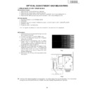
4. Press the "6" key on the keyboard. After the pattern
shown in Fig. 1 at right has appeared, press the
"R" key to get the red image displayed for checking.
Check the other colors as well (*1).
"R" key to get the red image displayed for checking.
Check the other colors as well (*1).
5. When part of the image does not appear in red,
loosen the wheel screw shown in Fig. 2 below and
slide the wheel sensor up or down. Fix the wheel
sensor again at the position where the color
deviation disappears.
slide the wheel sensor up or down. Fix the wheel
sensor again at the position where the color
deviation disappears.
6. Finally press the "Q" key on the keyboard to finish
the program.
Fig.1
●
1:The basic black and white patterns are registered in the numeric keys 0 thru 9 on the keyboard. The colors can be
changed to any of White(W), Black(K), Red(R), Green(G), Blue(B), Magenta(M) and Cyanic(C).
Wheel Screw
Wheel Sensor
Fig.2
18
PG-M10SU/SE
PG-M10XU/XE
PG-M10XU/XE
2.Measuring illuminance
●
Tools required
1. Personal computer (run on Windows 95/98)
2. Projection screen (normally white)
3. Light distribution point display program (Lumens.exe program commonly used for both models UP and U2)
4. Illumination meter
2. Projection screen (normally white)
3. Light distribution point display program (Lumens.exe program commonly used for both models UP and U2)
4. Illumination meter
●
Measuring lumen value
Connect the projector to the PC, and starts lighting.
Start up the light distribution point display program
(Lumens.exe) on the PC. Make the room dark. (A
darkroom is recommended.) Measure the illuminance
at the nine points shown at right. Put the measured
illuminance into the following equation to obtain the
lumen value.
Start up the light distribution point display program
(Lumens.exe) on the PC. Make the room dark. (A
darkroom is recommended.) Measure the illuminance
at the nine points shown at right. Put the measured
illuminance into the following equation to obtain the
lumen value.
B
A
Lumen value (L)
= (Average illuminance of 9 points) x (Projected area in m
2
)
={(P1+P2+ • • • +P9) / 9} x (A xB)
●
Evenness of illuminance
Put the measured illuminance into the following equation to obtain the evenness of illuminance.
Evenness of illuminance (%) = (The lowest illuminance measured out of 9 points) / (Average illuminance of 9 points)
= [MIN.(P1~P9) / {(P1+P2+ • • • +P9) / 9}] x 100
●
Peripheral illuminance ratio
Put the measured illuminance into the following equation to obtain the peripheral illuminance ratio.
Peripheral illuminance ratio (%) = (Average illuminance at P1, P3, P7 and P9) / (Illuminance at P5)
= {(P1+P3+P7+P9) / 4} / P5] x 100
The factory settings are as follows.
Model PG-M10X
Lumen value: Min. 500 Lm
Evenness of illuminance: Min. 50%
Peripheral illuminance ratio: Min. 80%
Model PG-M10S
Lumen value: Min. 500 Lm
Evenness of illuminance: Min. 50%
Peripheral illuminance ratio: Min. 80%
19
PG-M10SU/SE
PG-M10XU/XE
PG-M10XU/XE
3.Precautions in disassembling the optical mechanism
Color wheel
Once disassembled, this part may
need readjustment.
Once disassembled, this part may
need readjustment.
DMD assembly
This assembly can be disassembled. But be care-
ful not to allow dust and fingerprint on it. Otherwise
the images may be adversely affected.
This assembly can be disassembled. But be care-
ful not to allow dust and fingerprint on it. Otherwise
the images may be adversely affected.
Condenser lens ass'y
Spherical
mirror
mirror
Cylinder mirror
Do not separate the spherical
mirror and cylinder mirror from
the lens base (46).
mirror and cylinder mirror from
the lens base (46).
If the condenser lens or mirror has not
been correctly adjusted, there will be
shades on the projection screen.
(Usually shades appear on the right-
hand edge or at the bottom right cor-
ner of the screen.)
been correctly adjusted, there will be
shades on the projection screen.
(Usually shades appear on the right-
hand edge or at the bottom right cor-
ner of the screen.)

