Read Sharp PG-A10S (serv.man7) Service Manual online
16
PG-A10S
PG-A10S-SL
PG-A10S-SL
AN-A10T
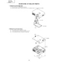
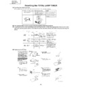
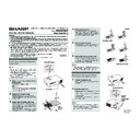
2. Removing the top body
2-1. Remove a screw from behind of the set.
2-2. Remove the six lock screws from bottom of the set.
2-3. Remove the two hooks and detach the top body.
2-2. Remove the six lock screws from bottom of the set.
2-3. Remove the two hooks and detach the top body.
2-1
2-3
2-3
2-2
Top Body
REMOVING OF MAJOR PARTS
1. Removing the lamp unit.
1-1. Loosen a screw and detach the lamp door.
1-2. Loosen the two screws. Hold the lamp unit by the handle and pull it in the direction of allow.
1-2. Loosen the two screws. Hold the lamp unit by the handle and pull it in the direction of allow.
1-1
Lamp Door
Lamp Unit
1-2
1-2
17
PG-A10S
PG-A10S-SL
PG-A10S-SL
AN-A10T
Operation Button
MAIN PWB
3-1
3-3
3-1
3-1
3-1
3-2
3-2
3-2
[FA]
[FC]
[EA]
[TF]
[FD]
[BP]
[GP]
[RP]
[FG]
[RC]
[LF]
[FE]
[TI]
[SP]
[FB]
[TH]
3-4
3. Removing the main PWB unit
3-1. Remove the seven screws.
3-2. Remove all the connectors from main PWB.
3-3. Detach the main PWB.
3-4. Remove the two screws and detach the operation
3-2. Remove all the connectors from main PWB.
3-3. Detach the main PWB.
3-4. Remove the two screws and detach the operation
button unit.
4. Removing the exhaust cover, optical mechanism unit, R/C receiver PWB
and speaker
4-1. Remove the two screws and detach the lamp socket.
4-2. Detach the Power/Ballast holder cover.
4-3. Remove all the connectors from optical mechanism unit.
4-4. Remove the nine screws and take out of the optical mechanism unit and the exhaust cover.
4-5. Detach the R/C receiver PWB.
4-6. Detach the Speaker.
4-2. Detach the Power/Ballast holder cover.
4-3. Remove all the connectors from optical mechanism unit.
4-4. Remove the nine screws and take out of the optical mechanism unit and the exhaust cover.
4-5. Detach the R/C receiver PWB.
4-6. Detach the Speaker.
Exhaust
Cover
Cover
Lamp
Socket
Socket
4-4
4-1
4-1
4-2
4-3
4-3
4-4
4-4
4-5
4-6
R/C Receiver PWB
Speaker
Optical mechanism unit
4-3
4-3
4-3
Power/Ballast
Holder Cover
Holder Cover
18
PG-A10S
PG-A10S-SL
PG-A10S-SL
AN-A10T
5. Removing the AC inlet, power/ballast unit and cooling fan
5-1. Remove a screw from behind of the set.
5-2. Remove a screw and take out of the power/ballast assembly.
5-3. Detach the bottom shield and shield cover.
5-4. Remove a connector and detach the AC inlet.
5-5. Remove the two hooks and take out of the ballast unit from power/ballast case. Remove the all connectors
5-2. Remove a screw and take out of the power/ballast assembly.
5-3. Detach the bottom shield and shield cover.
5-4. Remove a connector and detach the AC inlet.
5-5. Remove the two hooks and take out of the ballast unit from power/ballast case. Remove the all connectors
from power PWB.
5-6. Remove the two screws and detach the power PWB.
5-7. Remove the two screws and cooling fan.
5-7. Remove the two screws and cooling fan.
AC Inlet
Ballast Unit
Power PWB
Cooling Fan
Bottom Shield
Shield Cover
5-7
5-2
5-6
5-5
5-4
5-5
5-3
5-3
5-5
5-1
Note: When mounting the shield (bottom) for power supply/ballast (PSLDMA189WJFW) on the power supply/ballast
holder ass'y (CHLDZA135WJ01), make sure that it is inserted into the following place.
Be sure to insert the claw of the bottom shield into
the gap between the upper shield and holder.
the gap between the upper shield and holder.
After assembly, make sure that the claw of the bottom shield
is visible from the square hole on the upper shield.
is visible from the square hole on the upper shield.
* Never insert the claw be-
tween the insulating plate
and holder since the insu-
lating distance to the bal-
last PWB becomes inad-
equate.
and holder since the insu-
lating distance to the bal-
last PWB becomes inad-
equate.
19
PG-A10S
PG-A10S-SL
PG-A10S-SL
AN-A10T
6. Removing the intake duct assembly
6-1. Remove the two screws and take out of the intake duct assembly.
6-2. Remove a screw and detach the leaf switch.
6-3. Remove a screw and two hooks. Detach the the spacer B. Take out of the fan LCD R/G-intake duct B
6-2. Remove a screw and detach the leaf switch.
6-3. Remove a screw and two hooks. Detach the the spacer B. Take out of the fan LCD R/G-intake duct B
assembly.
6-4. Remove a screw and detach the fan LCD R/G.
6-5. Remove the two screws and detach the fan LCD B.
6-5. Remove the two screws and detach the fan LCD B.
6-1
6-2
6-3
6-5
6-4
6-3
6-3
Intake Duct B
Fan LCD R/G
Leaf Switch
Fan LCD B
6-5
6-3
Spacer B

