Read Sharp MX-RB13 (serv.man3) Service Manual online
MX-7040N MX-RB13 (RELAY UNIT) 18 – 1
MX-7040N
Service Manual
[18] MX-RB13 (RELAY UNIT)
1. Unpacking
A. Relay unit unpacking
NOTE: When moving the relay unit, use manpower of two or more
persons.
B. Fixing tape and protection material removal
1)
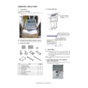
Remove the fixing tape and fixing bracket from the relay unit.
C. Packed items check
D. Cushion attachment
2. Installation
NOTE: Before installation, be sure to turn both the operation and
main power switches off and disconnect the power plug
from the power outlet. Make double sure that the data lamp
on the operation panel does not light up or blink when per-
forming installation.
from the power outlet. Make double sure that the data lamp
on the operation panel does not light up or blink when per-
forming installation.
NOTE: To prevent against falling during installation, extend the
stand rail.
A. Shunt cable connection plate installation
(Back of the relay unit)
1)
Fix the shunt cable connection plate (Packed items No.7) with
the screws (Packed items No.2).
the screws (Packed items No.2).
No.
Name
Quantity
1
Screw (M3 x 6 RS tight)
6
2
Screw (M4 x 8 RS tight)
8
3
Screw (M4 x 7 Round tup)
2
4
Latch receiver F
1
5
Latch receiver R
1
6
Earth bracket
1
7
Shunt cable connection plate
1
8
Rear upper cover
1
9
Paper guide D
1
10
Top surface cushion
1
1
2
3
4
5
6
7
8
9
10
Cushion attachment
position
position
Reference of cushion on.
(Rear screw hole tiered edge)
(Rear screw hole tiered edge)
Reference of cushion on.
(Upper cabinet lower edge)
(Upper cabinet lower edge)
MX-7040N MX-RB13 (RELAY UNIT) 18 – 2
B. Rear upper cover installation
1)
Attach the rear upper cover (Packed items No.8) and fix it with
the screw (Packed items No.3).
the screw (Packed items No.3).
C. Earth bracket installation
1)
Fix the earth bracket (Packed items No.6) with the screws
(Packed items No.1).
(Packed items No.1).
NOTE: Install the screws to the screw holes inside.
D. Connection plate installation
1)
Attach the safety plate (bundled with the inserter No.6) with the
screw (bundled with the inserter No.18).
screw (bundled with the inserter No.18).
2)
Fix the latch receivers F/R (Packed items No.4, 5) to the
inserter with the screws (Packed items No.2).
inserter with the screws (Packed items No.2).
E. Paper guide D installation
1)
Attach the Black Mylar (bundled with the inserter No.10) to the
paper guide D (Packed items No.9).
paper guide D (Packed items No.9).
Attach the Black Mylar to the downstream side of the paper
guide.
guide.
Attachment reference
Attach to the notch in the rear side as the reference.
2)
Fix the paper guide D (Packed items No.9) to the paper feed
side of the relay unit with the screws (Packed items No.1).
side of the relay unit with the screws (Packed items No.1).
F. Connection with the inserter
1)
Open the front cover of the relay unit, remove the screws and
pull the lock lever toward you.
pull the lock lever toward you.
R side
Black Mylar
Notch
1
MX-7040N MX-RB13 (RELAY UNIT) 18 – 3
2)
Connect the relay unit to the inserter.
Insert the pin in the inserter side into the hole in the relay unit.
Insert the pin in the inserter side into the hole in the relay unit.
Photo viewed from the R side
3)
Push up the lock lever to fix the relay unit and the inserter, and
use the removed screw to fix the lock lever.
use the removed screw to fix the lock lever.
MEMO: If they cannot be locked, follow the installing proce-
dures (height adjustment) of the complex machine and options
to adjust the height.
dures (height adjustment) of the complex machine and options
to adjust the height.
G. Height and tilt adjustment
NOTE: When the adjuster bolt is turned counterclockwise, the
height is decreased. When turned clockwise, the height is
increased.
increased.
NOTE: For the height and tilt adjustment, use the three adjuster
bolts under the unit.
Turn the adjustment nuts of the casters with a wrench in the arrow
direction to adjust the height. (When turning the adjustment nut one
rotation, the height of the relay unit is changed by about 1.75mm.)
direction to adjust the height. (When turning the adjustment nut one
rotation, the height of the relay unit is changed by about 1.75mm.)
• To increase the relay unit height, turn the nut in the direction [A].
• To decrease the relay unit height, turn the nut in the direction [B].
NOTE: Use the wrench attached to the finisher.
1)
Adjust the adjuster bolt (1) so that the difference in heights in
the front side the relay unit and the connection unit is within
2mm.
the front side the relay unit and the connection unit is within
2mm.
2)
Adjust the adjuster bolt (1) so that the difference in heights in
the rear side the relay unit and the connection unit is within
2mm.
the rear side the relay unit and the connection unit is within
2mm.
3)
Use adjuster bolt (3) so that the clearance between the
machine and the unit becomes uniform.
machine and the unit becomes uniform.
H. Cables attachment
1)
Open the cover at the back of the finisher, and disconnect the
dummy connector.
dummy connector.
2)
Attach the disconnected dummy connector to the saddle at the
right lower side to keep for future use.
Pass the cable from the relay unit to the center saddle and fix
with the screw (Packed items No.2) to connect.
right lower side to keep for future use.
Pass the cable from the relay unit to the center saddle and fix
with the screw (Packed items No.2) to connect.
3)
Connect the two cables, and attach the cover.
Ԙ
Ԛ
ԙ

