|
MX-M950 MX-MM1100 (serv.man6)
Virtual Manual
Service Manual
|
|
10.96 MB
|

|
MX-M950 MX-MM1100 (serv.man7)
Installation Manuals for Peripherals
Service Manual
|
|
6.67 MB
|
|
|
MX-M950 MX-MM1100 (serv.man8)
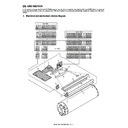
Details of each Section - M Waste Toner Section
Service Manual
|
3
|
809.92 KB
|

|
MX-M950 MX-MM1100 (serv.man9)
Main Machine
Service Manual
|
|
16.67 MB
|
|
|
MX-M950 MX-MM1100 (serv.man10)
Circuit Diagram
Service Manual
|
127
|
13.33 MB
|

|
MX-M950 MX-MM1100 (serv.man11)
Finishers Hole Punch Units
Service Manual
|
|
27.9 MB
|

|
MX-M950 MX-MM1100 (serv.man12)
Paper Feed Units
Service Manual
|
|
11.24 MB
|
|
|
MX-M950 MX-MM1100 (serv.man13)
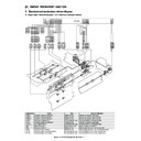
Details of Each Section - A External Outfit Section
Service Manual
|
4
|
1.49 MB
|
|
|
MX-M950 MX-MM1100 (serv.man14)
Details of Each Section - B Operation Panel
Service Manual
|
4
|
931.66 KB
|
|
|
MX-M950 MX-MM1100 (serv.man15)
Details of Each Section - C DSPF Section
Service Manual
|
27
|
7.66 MB
|
|
|
MX-M950 MX-MM1100 (serv.man16)
Details of Each Section - D Scanner Section
Service Manual
|
10
|
3.01 MB
|
|
|
MX-M950 MX-MM1100 (serv.man17)
Details of Each Section - E Tray Paper Feed Section
Service Manual
|
16
|
3.92 MB
|
|
|
MX-M950 MX-MM1100 (serv.man18)
Details of Each Section - F Paper Transport Section
Service Manual
|
15
|
3.89 MB
|
|
|
MX-M950 MX-MM1100 (serv.man19)
Details of Each Section - G LSU Section
Service Manual
|
4
|
895.21 KB
|
|
|
MX-M950 MX-MM1100 (serv.man20)
Details of Each Section - H Image Process Section
Service Manual
|
10
|
972.81 KB
|
|
|
MX-M950 MX-MM1100 (serv.man21)
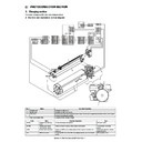
Details of Each Section - I Photoconductor Section
Service Manual
|
13
|
3.63 MB
|
|
|
MX-M950 MX-MM1100 (serv.man22)
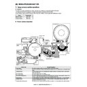
Details of Each Section - J Toner Supply Section
Service Manual
|
7
|
2.14 MB
|
|
|
MX-M950 MX-MM1100 (serv.man23)
Details of Each Section - K Developing Section
Service Manual
|
3
|
1.12 MB
|
|
|
MX-M950 MX-MM1100 (serv.man24)
Details of Each Section - L Transfer Section
Service Manual
|
5
|
1.54 MB
|
|
|
MX-M950 MX-MM1100 (serv.man25)
Details of Each Section - N Fusing Section
Service Manual
|
7
|
2.01 MB
|
|
|
MX-M950 MX-MM1100 (serv.man26)
Details of Each Section - O ADU Paper Exit Section
Service Manual
|
12
|
4.41 MB
|
|
|
MX-M950 MX-MM1100 (serv.man27)
Details of Each Section - P Drive Section
Service Manual
|
8
|
3.93 MB
|
|
|
MX-M950 MX-MM1100 (serv.man29)
Details of Each Section - R Fan Filter Section
Service Manual
|
7
|
2.03 MB
|
|
|
MX-M950 MX-MM1100 (serv.man30)
Details of Each Section - S Sensor Switch Section
Service Manual
|
3
|
923.53 KB
|
|
|
MX-M950 MX-MM1100 (serv.man31)
Front Back Covers
Service Manual
|
6
|
984.74 KB
|
|
|
MX-M950 MX-MM1100 (serv.man32)
Note For Servicing
Service Manual
|
2
|
557.83 KB
|
|
|
MX-M950 MX-MM1100 (serv.man33)
Section 1 Product Outline
Service Manual
|
4
|
687.19 KB
|
|
|
MX-M950 MX-MM1100 (serv.man34)
Section 2 Specifications
Service Manual
|
10
|
1.65 MB
|
|
|
MX-M950 MX-MM1100 (serv.man35)
Section 3 Consumable Parts
Service Manual
|
5
|
518.51 KB
|
|
|
MX-M950 MX-MM1100 (serv.man36)
Section 5 External View Intrenal Structure
Service Manual
|
22
|
1.58 MB
|
|
|
MX-M950 MX-MM1100 (serv.man37)
Section 6 Adjustments
Service Manual
|
82
|
10 MB
|
|
|
MX-M950 MX-MM1100 (serv.man38)
Section 7 Simulation
Service Manual
|
103
|
1.17 MB
|
|
|
MX-M950 MX-MM1100 (serv.man39)
Section 8 Self Diagnostics Trouble Codes
Service Manual
|
33
|
770.78 KB
|
|
|
MX-M950 MX-MM1100 (serv.man40)
Section 9 Maintenance
Service Manual
|
86
|
27.14 MB
|
|
|
MX-M950 MX-MM1100 (serv.man41)
Section 10 Rom Version Up
Service Manual
|
3
|
892.26 KB
|
|
|
MX-M950 MX-MM1100 (serv.man42)
Section 11 Electrical
Service Manual
|
56
|
3.89 MB
|
|
|
MX-M950 MX-MM1100 (serv.man43)
Section 12 Others
Service Manual
|
18
|
1.67 MB
|

|
MX-M950 MX-MM1100 (serv.man44)
Peripherals (All)
Service Manual
|
|
28.17 MB
|
|
|
MX-M950 MX-MM1100 (serv.man49)
Guide to Booklet Making
User Guide / Operation Manual
|
38
|
1.76 MB
|
|
|
MX-M950 MX-MM1100 (serv.man50)
User Manual
User Guide / Operation Manual
|
96
|
2.14 MB
|

|
MX-M950 MX-MM1100 (serv.man114)
EFI PCL Print Driver. Windows XP
Drivers
|
|
5.12 MB
|

|
MX-M950 MX-MM1100 (serv.man115)
EFI Postscript Print Driver. Windows XP
Drivers
|
|
4.75 MB
|
|
|
MX-M950 MX-MM1100 (serv.man45)
Parts Guide (Revised December 2016).
Parts Guide
|
127
|
27.48 MB
|
|
|
MX-M950 MX-MM1100 (serv.man46)
MFX1 (Multi Bypass Tray)
Parts Guide
|
15
|
1.69 MB
|
|
|
MX-M950 MX-MM1100 (serv.man47)
FDX1 (Folding Unit)
Parts Guide
|
34
|
6.16 MB
|
|
|
MX-M950 MX-MM1100 (serv.man48)
MFX2 (Multi Bypass Tray)
Parts Guide
|
14
|
1.5 MB
|
|
|
MX-M950 MX-MM1100 (serv.man5)
Sharp Media Guide
Specification
|
54
|
2.6 MB
|
|
|
MX-M950 MX-MM1100 (serv.man66)
Parts change for productivity improvement.
Technical Bulletin
|
3
|
184.15 KB
|

|
MX-M950 MX-MM1100 (serv.man67)
MFX1 - DESIGN CHANGE OF MF TRAY 2 UPPER
Technical Bulletin
|
|
143.26 KB
|
|
|
MX-M950 MX-MM1100 (serv.man68)
Enhancement of LC13 Main Drive Gear
Technical Bulletin
|
3
|
760.63 KB
|
|
|
MX-M950 MX-MM1100 (serv.man69)
MFX1 Parts Change
Technical Bulletin
|
2
|
674.63 KB
|
|
|
MX-M950 MX-MM1100 (serv.man70)
Starting Powder List (This list takes priority over information in Service Manuals).
Technical Bulletin
|
4
|
66.25 KB
|
|
|
MX-M950 MX-MM1100 (serv.man71)
NEWLY-REGISTERED SERVICE PARTS FOR FINISHERS
Technical Bulletin
|
5
|
931.93 KB
|
|
|
MX-M950 MX-MM1100 (serv.man72)
Recommended shutdown procedure and Power Cycling of MFD
Technical Bulletin
|
1
|
186.43 KB
|
|
|
MX-M950 MX-MM1100 (serv.man73)
IMPORTANT Handling of EEPROM's.
Technical Bulletin
|
5
|
203.32 KB
|
|
|
MX-M950 MX-MM1100 (serv.man74)
Change of mounting screw for exhaust duct reinforce plate
Technical Bulletin
|
2
|
443.61 KB
|
|
|
MX-M950 MX-MM1100 (serv.man75)
Change of shape of the polygon motor in the LSU
Technical Bulletin
|
2
|
123.26 KB
|
|
|
MX-M950 MX-MM1100 (serv.man76)
Change in the packing of the developer.
Technical Bulletin
|
1
|
45.62 KB
|
|
|
MX-M950 MX-MM1100 (serv.man77)
Paper Jams (FDSBD_NA, ETC.) caused by fusing read torque limiter slipping.
Technical Bulletin
|
2
|
52.32 KB
|
|
|
MX-M950 MX-MM1100 (serv.man78)
Rom Upgrade (11)
Technical Bulletin
|
1
|
17.87 KB
|
|
|
MX-M950 MX-MM1100 (serv.man79)
FIX TO INCREASE THE MARGIN THAT THE FAN MOTOR FASTENER WILL NOT BECOME STRIPPED
Technical Bulletin
|
2
|
41.49 KB
|
|
|
MX-M950 MX-MM1100 (serv.man80)
Improvements to dust resistance of the DSPF scanner
Technical Bulletin
|
4
|
319.04 KB
|
|
|
MX-M950 MX-MM1100 (serv.man81)
PRECAUTIONS WHEN INSERTING A TONER CARTRIDGE
Technical Bulletin
|
1
|
15.47 KB
|
|
|
MX-M950 MX-MM1100 (serv.man82)
F1-09, F1-11 and BLTJAM Codes
Technical Bulletin
|
1
|
86.3 KB
|
|
|
MX-M950 MX-MM1100 (serv.man83)
Rom Update (9) To (10)
Technical Bulletin
|
4
|
27.79 KB
|
|
|
MX-M950 MX-MM1100 (serv.man84)
ISSUING EXPLANATORY MATERIAL OF JOB LOG CODES.
Technical Bulletin
|
13
|
160.14 KB
|
|
|
MX-M950 MX-MM1100 (serv.man85)
Adhesion of dirt on drum separator pawl transtering to the paper edge
Technical Bulletin
|
1
|
30.14 KB
|
|
|
MX-M950 MX-MM1100 (serv.man86)
POIND_N Jams due to paper sticking to the OPC drum
Technical Bulletin
|
1
|
47.23 KB
|
|
|
MX-M950 MX-MM1100 (serv.man87)
CHANGE OF INITIAL VALUES OF PREHEAT MODE AND AUTO POWER SHUT-OFF MODE OF ENERGY STAR VER1.1
Technical Bulletin
|
2
|
20.01 KB
|
|
|
MX-M950 MX-MM1100 (serv.man88)
Rom Upgrade (8)
Technical Bulletin
|
3
|
25.99 KB
|
|
|
MX-M950 MX-MM1100 (serv.man89)
PAPER FEED JAMS (DPFD1_N4, ETC.)
Technical Bulletin
|
2
|
55.54 KB
|
|
|
MX-M950 MX-MM1100 (serv.man90)
Intermittent background on copies or prints
Technical Bulletin
|
1
|
1.04 MB
|
|
|
MX-M950 MX-MM1100 (serv.man91)
Rom Update (7)
Technical Bulletin
|
2
|
22.88 KB
|
|
|
MX-M950 MX-MM1100 (serv.man92)
Service parts for the draw connectors mounted on the ADU and on the machine frame.
Technical Bulletin
|
2
|
61.59 KB
|
|
|
MX-M950 MX-MM1100 (serv.man93)
REF 25 Special Firmware Update For changes to Pamphlet mode, Z Folding mode Page inserts Please read carefully before installing Firmware
Technical Bulletin
|
4
|
149.52 KB
|
|
|
MX-M950 MX-MM1100 (serv.man94)
Rustproof paper guide for the ADU paper exit unit
Technical Bulletin
|
2
|
37.08 KB
|
|
|
MX-M950 MX-MM1100 (serv.man95)
REF 23 -Countermeasures for preventing breakages of the drawer connectors of the ADU exit unit.
Technical Bulletin
|
2
|
64.17 KB
|
|
|
MX-M950 MX-MM1100 (serv.man96)
Preventing the malfunction of the operation panel.
Technical Bulletin
|
2
|
137.64 KB
|
|
|
MX-M950 MX-MM1100 (serv.man97)
Reducing uneven charge (image steaking)
Technical Bulletin
|
2
|
20.51 KB
|
|
|
MX-M950 MX-MM1100 (serv.man98)
Countermeasures taken when toner is not supplied due to disconnection of toner hopper unit harness - (F2-02 Error code)
Technical Bulletin
|
3
|
159.48 KB
|
|
|
MX-M950 MX-MM1100 (serv.man99)
HDD Replacment
Technical Bulletin
|
5
|
94.47 KB
|
|
|
MX-M950 MX-MM1100 (serv.man100)
ROM UPGRADE 0200H0
Technical Bulletin
|
2
|
19.39 KB
|
|
|
MX-M950 MX-MM1100 (serv.man101)
ICU 0110H0
Technical Bulletin
|
3
|
18.46 KB
|
|
|
MX-M950 MX-MM1100 (serv.man102)
REF 014 Improvement in irregular print image at an irregular pitch
Technical Bulletin
|
2
|
56.54 KB
|
|
|
MX-M950 MX-MM1100 (serv.man103)
REF 011 Transfer roller bearing added to the Transfer belt kit (MX-850TT)
Technical Bulletin
|
2
|
23.53 KB
|
|
|
MX-M950 MX-MM1100 (serv.man104)
REF 010 Revision of maintenance manuals
Technical Bulletin
|
1
|
18.2 KB
|
|
|
MX-M950 MX-MM1100 (serv.man105)
REF 009 Revisions to the installation Manual
Technical Bulletin
|
2
|
375.33 KB
|
|
|
MX-M950 MX-MM1100 (serv.man106)
Information about the revisions of the main unit service manual
Technical Bulletin
|
3
|
615.68 KB
|
|
|
MX-M950 MX-MM1100 (serv.man107)
Change of a screw tightening for tray 3 of the main unit
Technical Bulletin
|
3
|
209.24 KB
|
|
|
MX-M950 MX-MM1100 (serv.man108)
Rom Upgrade
Technical Bulletin
|
2
|
16.13 KB
|
|
|
MX-M950 MX-MM1100 (serv.man109)
Consideration Concerning Installation of the MX-FXX1
Technical Bulletin
|
3
|
253.32 KB
|

|
MX-M950 MX-MM1100 (serv.man56)
MXM850 950 1100 Firmware for Equitrac issue. 02.06.H0o_B
Driver / Update
|
|
27.56 MB
|

|
MX-M950 MX-MM1100 (serv.man57)
New Special Firmware Original dated 30.07.08 V1 firmware for 1 sheet pamphlet w o stapling,Combination with punch and z folding Z folding with cover in copy mode to work with Macronix PCU chips
Driver / Update
|
|
27.44 MB
|

|
MX-M950 MX-MM1100 (serv.man58)
Sleep Mode and Under Load
Driver / Update
|
|
27.68 MB
|

|
MX-M950 MX-MM1100 (serv.man59)
SAP Device Types for MX Mono devices.
Driver / Update
|
|
3.18 MB
|

|
MX-M950 MX-MM1100 (serv.man60)
Includes Tech Bulletin
Driver / Update
|
|
27.7 MB
|

|
MX-M950 MX-MM1100 (serv.man61)
ICU 0206H0 - Inc Tech Bulletin
Driver / Update
|
|
27.6 MB
|

|
MX-M950 MX-MM1100 (serv.man62)
Fixed Equitrac Firmware (0206H0c0_B)
Driver / Update
|
|
27.56 MB
|

|
MX-M950 MX-MM1100 (serv.man63)
30.07.08 Special Firmware Update V2. For changes to spec to pamphlet mode, Z Folding when there is a specific need to increase the page insets function. ONLY install when MX-PBX2 is fitted. Read Tech Bulletin 1st
Driver / Update
|
|
27.59 MB
|

|
MX-M950 MX-MM1100 (serv.man64)
Linux PPD for MXM850 950 1100 for use with CUPS.
Driver / Update
|
|
356.95 KB
|

|
MX-M950 MX-MM1100 (serv.man65)
PC Fax Driver (MX-FXX1)
Driver / Update
|
|
17.16 MB
|
|
|
MX-M950 MX-MM1100
EEPROM Programming Procedure
Handy Guide
|
4
|
772.27 KB
|
|
|
MX-M950 MX-MM1100 (serv.man2)
New Configuration and Installation Guide v3.6
Handy Guide
|
21
|
4.88 MB
|
|
|
MX-M950 MX-MM1100 (serv.man3)
39906
Handy Guide
|
21
|
4.31 MB
|
|
|
MX-M950 MX-MM1100 (serv.man4)
May 08
Handy Guide
|
54
|
872.01 KB
|
|
|
MX-M950 MX-MM1100 (serv.man51)
How To Read A Main Machine Serial Number
FAQ
|
1
|
16.5 KB
|
|
|
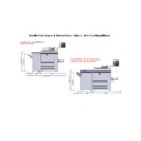
MX-M950 MX-MM1100 (serv.man52)
Foot space required for all machine and option configuations
FAQ
|
6
|
725.01 KB
|
|
|
MX-M950 MX-MM1100 (serv.man53)
Power Requirments for all Hercules Models
FAQ
|
1
|
190.11 KB
|

|
MX-M950 MX-MM1100 (serv.man54)
PCL PJL PS COMMANDS FOR MXM850 950 1100
FAQ
|
|
84.04 KB
|
|
|
MX-M950 MX-MM1100 (serv.man55)
How to connect MXM850 950 1100 to Linux UNIX systems using CUPS.
FAQ
|
9
|
1.14 MB
|
|
|
MX-M950 MX-MM1100 (serv.man110)
MXM1100
Regulatory Data
|
1
|
39.33 KB
|
|
|
MX-M950 MX-MM1100 (serv.man111)
MXM950
Regulatory Data
|
1
|
39.35 KB
|
|
|
MX-M950 MX-MM1100 (serv.man112)
MX-850GV (Black Developer) MSDS No F-31491
Regulatory Data
|
4
|
296.69 KB
|
|
|
MX-M950 MX-MM1100 (serv.man113)
MX-850GT (Black Toner) MSDS No F-01491
Regulatory Data
|
4
|
36.5 KB
|

