Read Sharp MX-M850 (serv.man18) Service Manual online
MX-M1100 LSU SECTION G – 1
MX-M1100
Service Manual
[G] LSU SECTION
In this section, the image data from W-ICU PWB (image process circuit) is converted to video data by LSU control PWB. Next, it is converted
by the laser diode to from a beam, and exposes to the OPC drum surface. As a result, latent electrostatic images are formed on the OPC drum
surface.
by the laser diode to from a beam, and exposes to the OPC drum surface. As a result, latent electrostatic images are formed on the OPC drum
surface.
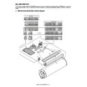
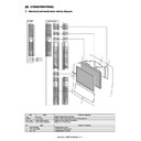
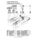
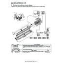
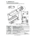
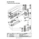
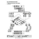
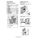
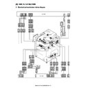
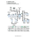
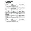
1. Electrical and mechanism relation diagram
3
1
2
10
14
4
5
15
16
6
7
8
9
11
12
13
3
1
+5V_LD
1
1
+5V_LD
4
2
GND2
2
2
GND2
GND2
1
B04B-PASK-1
CN3
B06B-PASK-1
CN4
4
GND2
B04B-PASK
GND2
5
5
3
GND2
3
3
GND2
/BD
2
3
/BD
GND2
6
6
4
GND2
4
4
GND2
GND2
3
2
GND2
GND2
7
7
5
GND2
5
5
GND2
+5V_C
4
1
+5V_C
+3.3V_P
8
8
6
+3.3V_P
6
6
+3.3V_P
SCK_LSU
9
9
7
SCK_LSU
7
7
SCK_LSU
GND2
10
8
GND2
8
8
GND2
TRANS_DAT
11
9
TRANS_DAT
9
9
TRANS_DAT
+5V_C
12
10
+5V_C
10
10
+5V_C
LSU_RST
13
11
LSU_RST
11
11
LSUASIC
R
ST
+24V_A
14
12
+24V_A
12
12
+24V4_A
/ENB_K
1
1
1
/ENB_K
RSV_DAT
15
13
RSV_DAT
13
13
RSV_DAT/
GND2
2
2
2
GND2
GND2
16
14
GND2
14
14
GND1
DATA-_K4
3
3
3
DATA-_K4
TRANS_RST
17
15
TRANS_RST
15
15
TRANS_RST/
VREF_K4
4
4
4
VREF_K4
GND2
18
16
GND2
16
16
GND2
DATA+_K4
5
5
5
DATA+_K4
JOBEND
19
17
JOBEND
17
17
JOBEND_INT
/SH_K4
6
6
6
/SH_K4
GND2
20
18
GND2
18
18
GND2
GND2
7
7
7
GND2
LSU_FPGA_DONE
21
19
LSU_FPGA_DONE
19
19
LSU_FPGA_DONE
/LDERR2
8
8
8
/LDERR2
LSU_FPGA_SEL
22
20
LSU_FPGA_SEL
20
20
LSU_FPGA_SEL
DATA-_K3
9
9
9
DATA-_K3
LSU_FPGA_ST
23
21
LSU_FPGA_ST
21
21
LSU_FPGA_ST
VREF_K3
10
10
VREF_K3
LSU_FPGA_PROGRAM
24
22
LSU_FPGA_PROGRAM
22
22
LSU_FPGA_PROGRAM
DATA+_K3
11
11
DATA+_K3
GND2
25
23
(NC)
23
23
/BEAMDETECT
/SH_K3
12
12
/SH_K3
GND2
26
24
GND2
24
24
GND2
S24B-PADSS-1
CN2
GND2
13
13
GND2
/LDERR1
14
14
/LDERR1
B34B-PNDZS-1
CN-5
DATA-_K2
15
15
DATA-_K2
VREF_K2
16
16
VREF_K2
DATA+_K2
17
17
DATA+_K2
/SH_K2
18
18
/SH_K2
GND2
19
19
GND2
LDCHK2
20
20
LDCHK2
DATA-_K1
21
21
DATA-_K1
VREF_K1
22
22
VREF_K1
DATA+_K1
23
23
DATA+_K1
/SH_K1
24
24
/SH_K1
LSU_CH0_N
BM30B-SHLDS-G-TFT
CN8
1
1
LSU_CH0_N
SM30B-SHLDS-G-TFT
BM30B-SHLDS-G-TFT
CN5
CN1
GND2
25
25
GND2
GND2
2
2
GND2
LDCHK1
26
26
LDCHK1
LSU_CH0_P
3
3
LSU_CH0_P
GND2
27
27
GND2
LSU_VSYNCY_N
4
4
LSU_VSYNCY_N
GND2
28
28
GND2
GND2
5
5
GND2
+5V_LD
29
29
+5V_LD
LSU_VSYNCY_P
6
6
LSU_VSYNCY_P
GND2
30
30
GND2
LSU_CH1_N
7
7
LSU_CH1_N
LSU_VSYNCM_P
8
8
LSU_VSYNCM_P
LSU_CH1_P
9
9
LSU_CH1_P
LSU_VSYNCM_N
10
10
LSU_VSYNCM_N
GND2
11
11
GND2
LSU_VSYNCC_N
12
12
LSU_VSYNCC_N
LSU_CH2_N
13
13
LSU_CH2_N
LSU_VSYNCC_P
14
14
LSU_VSYNCC_P
LSU_CH2_P
15
15
LSU_CH2_P
LSU_VSYNCK_P
16
16
LSU_VSYNCK_P
GND2
17
17
GND2
LSU_VSYNCK_N
18
18
LSU_VSYNCK_N
LSU_CLK_N
19
19
LSU_CLK_N
GND2
20
20
GND2
LSU_CLK_P
21
21
LSU_CLK_P
LSU_HSYNC_N
22
22
LSU_HSYNC_N
GND2
23
23
GND2
+24V
1
1
6
+24V
B06B-PASS-TFT
BM30B-SHLDS-G-TFT
LSU_HSYNC_P
24
24
LSU_HSYNC_P
GND1
2
2
5
GND1
LSU_CH3_N
25
25
LSU_CH3_N
nPOLY_START
3
3
4
nPOLY_START
GND2
26
26
GND2
nPOLY_LOCK
4
4
3
nPOLY_LOCK
LSU_CH3_P
27
27
LSU_CH3_P
nPOLY_CK
5
5
2
nPOLY_CK
LSU_ECLK_P
28
28
LSU_ECLK_P
nBRAKE
6
6
1
nBRAKE
GND2
29
29
GND2
LSU_ECLK_N
30
30
LSU_ECLK_N
+5V_LD
GND2
PCU PWB
W-ICU PWB
LSU PWB
MX-M1100 LSU SECTION G – 2
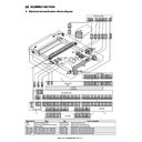
2. Operational descriptions
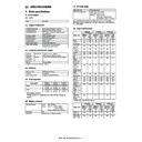
This LSU emits 4 laser beams during 1200dpi mode and 2 laser beams during 600dpi mode.
The operation varies as below according to the model and the print mode. (resolution)
The operation varies as below according to the model and the print mode. (resolution)
(* 1):
The laser beam size is the same regardless of the print resolution 600dpi or 1200dpi, but the laser power varies.
When the laser beams are applied to the photoreceptor to form the electrostatic latent image, the more the laser power is, the larger the area of
the electrostatic latent image created by 1 dot of the laser beam becomes.
This occurs because of optical characteristics of the photoreceptor. The laser power of 600dpi is higher than 1200dpi, so the area of the elec-
trostatic latent image created by 1 dot of the 600dpi laser becomes larger than that of 1200dpi laser.
That effect prevents from creating difference in print density among images with different resolution.
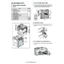
3. Disassembly and assembly
A. LSU
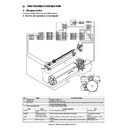
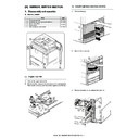
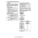
(1) LSU
1)
Remove the left upper cabinet.
2)
Disconnect the connector (a),and remove the screw (b).
Remove the LSU (c).
Remove the LSU (c).
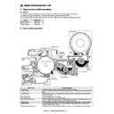
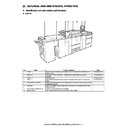
No
Name
Function
1
Scanning mirror (Polygon mirror motor)
Reflects the laser beam to expose the drum surface. Writes in the main scan direction.
2
Laser unit
Emits the laser beam.
3
No.1 cylindrical lens
Gathers the laser beams from the laser unit.
4
Incident mirror
Reflects the laser beams from the laser unit to send to the scanning mirror.
5
No.1 mirror
Reflects the laser beams from the scanning mirror to send to No.2 mirror.
6
No.2 mirror
Reflects the laser beams from No.1 mirror to send to No.3 mirror.
7
No.3 mirror
Reflects the laser beams from No.2 mirror to send to the photoreceptor.
8
No.2 cylindrical lens
Corrects the deflection caused by the tilted scanning mirror.
9
BD mirror
Guides the laser beams to BD PWB.
10
BD PWB
Detects the start timing of the laser scan.
Detects the troubles of laser beams.
Detects the troubles of laser beams.
11
f lens 2
Bends the laser beams to equalize the laser scanning pitches on the OC drum.
12
Filter glass
Prevents contamination of dusts and foreign material.
13
f lens 1
Bends the laser beams to equalize the laser scanning pitches on the OC drum.
14
Laser control PWB
Converts the image signals to video signals and laser beams.
Controls ON/OFF and output power of the laser.
Controls ON/OFF and output power of the laser.
15
Filter glass
Prevents contamination of dusts and foreign material from the outside.
16
Distortion adjustment cam
The cam for adjusting distortion of the print image.
Model
Number of
scanning
mirrors
Number of
revolutions of the
scanning mirror
Laser power
Number of laser beams
per scan
(Main scanning direction)
Laser beam
size (*1)
Laser beam pitch
(Main scanning
direction)
600 dpi
1200 dpi
600 dpi
1200 dpi
600 dpi
1200 dpi
85-sheet model
14 faces
20,247 rpm
0.21 mw
0.12 mw
2
4
60um
✕ 60um
42
μm
21
μm
95/100-sheet model
14 faces
27,334 rpm
0.28 mw
0.15 mw
2
4
60um
✕ 60um
42
μm
21
μm
Parts
Page
A
LSU
G - 2/(1)
B
Temperature humidity sensor 2
G - 3/(2)
A
B
a
a
b
b
c
MX-M1100 LSU SECTION G – 3
(2) Temperature humidity sensor 2
1)
Remove the rear cabinet.
2)
Remove the upper cabinet left, the upper cabinet right, the
upper cabinet front cover right, and the upper cabinet front
cover left.
upper cabinet front cover right, and the upper cabinet front
cover left.
3)
Open the front cover (a), and pull out the toner tray (b) slightly.
4)
Remove the screw (a), and remove the cover (b).
5)
Remove the screw (a), and remove the front cover (b).
6)
Pull out the toner tray (a), and remove the toner bottle (b).
7)
Remove the screw (a), and remove the toner tray (b).
8)
Remove the screw (a), and remove the cover (b).
a
b
a
a
b
a
a
a
a
b
a
b
a
a
a
a
a
a
b
a
b
a
MX-M1100 LSU SECTION G – 4
9)
Disconnect the connector (a), and remove the screw (b).
Remove the duct unit (c).
Remove the duct unit (c).
10) Disconnect the connector (a), and remove the temperature
humidity sensor 2 (b).
a
b
b
c
b
a

