Read Sharp MX-M850 (serv.man15) Service Manual online
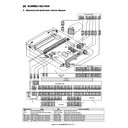
MX-M1100 SCANNER SECTION D – 1
MX-M1100
Service Manual
[D] SCANNER SECTION
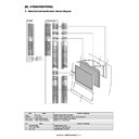
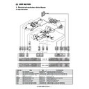
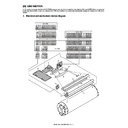
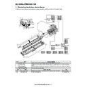
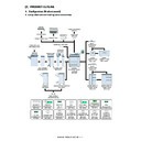
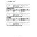
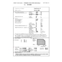
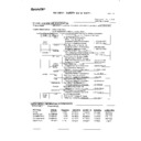
1. Electrical and mechanism relation diagram
Signal name
Name
Type
Function / Operation
MIM
Scanner (reading) motor
Stepping motor
Drives the copy lamp unit.
MHPD
Scanner home position sensor detector
Photo interrupter
Scanner home position detection.
CLI
Scanner lamp
Xenon lamp
SEL_ANIN 1
Reflectin type
SEL_ANIN 2
Reflectin type
SEL_ANIN 4
Reflectin type
SEL_IN 5
Reflectin type
MHPS
MHPS
SEL_ANIN4
SEL_ANIN4
TH_CL
TH_CL
SEL_ANIN2
SEL_ANIN2
SEL_ANIN1
SEL_ANIN1
SEL_IN5
SEL_IN5
CLI
CLI
SEL_IN6
SEL_IN6
SEL_IN7
SEL_IN7
SEL_IN8
SEL_IN8
MIM
MIM
CLFM
CLFM
CCDFM
CCDFM
CCD PWB
CCD PWB
1
4
3
2
S3B-PASK-2
1
CCD_FAN_Power
1
1
CCD_FAN_Power
2
CCD_FAN_LOCK
2
2
CCD_FAN_LOCK
3
GND
3
3
GND
S16B-PASK-2
CN4
+5V_C#
1
1+
5
V
_
C
#
GND
2
2G
N
D
PD_CLKOUT8
3
3
PD_CLKOUT8
SEL_IN_8
4
4
SEL_IN_8
5+
5
V
_
C
#
6G
N
D
+5V_C#
1
7
PD_CLKOUT7
GND
2
8
SEL_IN_7
PD_CLKOUT7
3
9+
5
V
_
C
#
SEL_IN_7
4
10
GND
11
PD_CLKOUT6
12
SEL_IN_6
+5V_C#
1
13
+5V_C#
GND
2
14
GND
PD_CLKOUT6
3
15
PD_CLKOUT5
SEL_IN_6
4
16
SEL_IN_5
+5V_C#
1
GND
2
PD_CLKOUT5
3
SEL_IN_5
4
MM_/A
2
MM_/B
3
MM_A
4
MM_B
5
S15B-PASK-2
CN6
1
MM_/A
2
MM_/B
3
MM_A
4
MM_B
CL_FAN_Power
1
1
CL_FAN_Power
4
5
CL_FAN_Power
PGND
2
2
PGND
3
6
PGND
CL_FAN_LOCK
3
3
CL_FAN_LOCK
2
7
CL_FAN_LOCK
(NC)
4
4
(NC)
1
SCN_Mother PWB
PAP-03V-S/PALR-03VF
BU04P-TR-P-H
CN3
BM20B_SHLDS_G-TFT
CN6
B06B-XASK-1
S06B-PASK-2
CN2
CN9
+24V_A6#
1
1
+24V_A6#
+24V_A6#
2
2
+24V_A6#
ON/OFF
3
3
ON/OFF
INV_CLK
4
4
INV_CLK
PGND
5
5
PGND
PGND
6
6
PGND
CN1
BM20B_SHLDS_G-TFT
SCANDATA2+
1
1
SCANDATA2+
SCANCLKOUT-
2
2
SCANCLKOUT-
SCANDATA2-
3
3
SCANDATA2-
SCANCLKOUT+
4
4
SCANCLKOUT+
BM50B-SHLDS-G-TFT
SM50B-SHLDS-G-TF
GND
5
5
GND
AGND
49
1
GND
GND
6
6
GND
ICLP-
47
3
ICLP-
SCANDATA1+
7
7
SCANDATA1+
ICLP+
45
5
ICLP+
SCANDATA3-
8
8
SCANDATA3-
BM20B-SHLDS-G-TFT
CN1
BM30B-SHLDS-G-TFT
CN1
CN3
AGND
43
7
GND
SCANDATA1-
9
9
SCANDATA1-
AGND
1
29
AGND
AFE_SEN-F
41
9
AFE_SEN-F
SCANDATA3+
10
10
SCANDATA3+
CCD
CP-
3
27
CCD
CP-
AFE_SEN-R
39
11
AFE_SEN-R
GND
11
11
GND
CCD
CP+
5
25
CCD
CP+
AFE_SCLK
37
13
AFE_SCLK
GND
12
12
GND
AGND
7
21
AGND
AFE_RESET
35
15
AFE_RESET
SCANDATA0+
13
13
SCANDATA0+
CCD
RS
+
9
19
CCD
RS+
PDWNB
33
17
PDWNB
WICU_nREQACK_OUT
14
14
WICU_nREQACK_OUT
CCD
RS
-
11
17
CCD
RS-
AGND
31
19
GND
SCANDATA0-
15
15
SCANDATA0-
AGND
13
13
AGND
SH_OUT+
29
21
SH_OUT+
WICU_nREQACK_IN
16
16
WICU_nREQACK_IN
CCD
SH
-
15
11
CCD
SH-
SH_OUT-
27
23
SH_OUT-
GND
17
17
GND
CCD
SH
+
17
9
CCD
SH+
AGND
25
25
GND
nSCN_STATE2
18
18
nSCN_STATE2
Reg
O
N_OFF
19
3
Reg
ON_OFF
LVDS_CLK-
23
27
LVDS_CLK-
GND
19
19
GND
AGND
2
30
AGND
LVDS_CLK+
21
29
LVDS_CLK+
nSCN_STATE1
20
20
nSCN_STATE1
CCD
1
-
4
28
CCD
1-
AGND
19
31
GND
CN3
CCD
1
+
6
26
CCD
1+
CCD
SH+
17
33
CCD
S
H+
B15B-PASK-1
CN5
B15B-PASK-1
AGND
8
22
AGND
CCD
SH-
15
35
CCD
S
H-
RxD_WICU(+)
1
1
RxD_WICU(+)
CCD
2+
10
20
CCD
2+
AGND
13
37
GND
RxD_WICU(-)
2
2
RxD_WICU(-)
CCD
2-
12
18
CCD
2-
CCD
RS-
11
39
CCD
R
S-
GND
3
3G
N
D
AGND
14
1
AGND
CCD
RS+
9
41
CCD
R
S+
TxD_WICU(+)
4
4
TxD_WICU(+)
+5V_C#
16
8
+5V_C#
AGND
7
43
GND
TxD_WICU(-)
5
5
TxD_WICU(-)
+12V_C#
18
4
+12V_C#
CCD
CP+
5
45
CCD
C
P+
GND
6
6G
N
D
AGND
20
2
AGND
CCD
CP-
3
47
CCD
C
P-
nCTS_WICU
7
7
n
CTS_WICU
24
AGND
Reg_ON/OFF
1
49
Reg_ON/OFF
nRTS_WICU
8
8
n
RTS_WICU
23
AGND
AGC_EN
50
2
AGC_EN
RES_WICU
9
9
R
ES_WICU
16
AGND
+5V_C#
48
4
+5V_C#
FWP_WICU
10
10
FWP_WICU
15
AGND
CLP_ND_EN
46
6
CLP_ND_EN
nPOF_WICU
11
11
nPOF_WICU
14
AGND
FCLP_SEL
44
8
FCLP_SEL
GND
1
2
12
GND
12
AGND
AFE_SDI
42
10
AFE_SDI
GND
1
3
13
GND
10
AGND
AFE_SDO
40
12
AFE_SDO
GND
1
4
14
GND
7
AGND
AGND
38
14
GND
GND
1
5
15
GND
6
AGND
BLKCLP-
36
16
BLKCLP-
5
AGND
BLKCLP+
34
18
BLKCLP+
AGND
32
20
GND
CLP+
30
22
CLP+
CLP-
28
24
CLP-
AGND
26
26
GND
AD_MCLK-
24
28
AD_MCLK-
AD_MCLK+
22
30
AD_MCLK+
AGND
20
32
GND
+12V_C#
18
34
+12V_C#
BM20B-SHLDS-G-TFT
CN2
501190-2017
CN2
+5V_C#
16
36
+5V_C#
AGND
1
19
AGND
AGND
14
38
GND
A3.3V_C#
2
20
A3.3V_C#
CCD
2
-
12
40
CCD
2
-
RODD-R
3
15
RODD-R
CCD
2
+
10
42
CCD
2
+
REVEN-R
4
17
REVEN-R
AGND
8
44
GND
RODD-F
5
18
RODD-F
CCD
1
+
6
46
CCD
1
+
REVEN-F
6
16
REVEN-F
CCD
1
-
4
48
CCD
1
-
AGND
7
13
AGND
AGND
2
50
GND
AGND
8
14
AGND
GODD-R
9
9
GODD-R
GEVEN-R
10
11
GEVEN-R
GODD-F
11
12
GODD-F
GEVEN-F
12
10
GEVEN-F
AGND
13
7
AGND
BM40B-SHLDS-G-TFT
CN4
SM40B-SHLDS-G-TF
CN8
AGND
14
8
AGND
AGND
39
1
GND
BODD-R
15
3
BODD-R
TC
+F
37
3
TC
+F
BEVEN-R
16
5
BEVEN-R
TC
-F
35
5
TC
-F
BODD-F
17
6
BODD-F
AGND
33
7
GND
BEVEN-F
18
4
BEVEN-F
TB
+F
31
9
TB
+F
AGND
19
1
AGND
TB
-F
29
11
TB
-F
AGND
20
2
AGND
AGND
27
13
GND
TA
+F
25
15
TA
+F
TA
-F
23
17
TA
-F
AGND
21
19
GND
AGND
19
21
GND
TE
+R
17
23
TE
+R
TE
-R
15
25
TE
-R
AGND
13
27
GND
TD
+R
11
29
TD
+R
TD
-R
9
31
TD
-R
AGND
7
33
GND
TCLK
+R
5
35
TCLK
+R
TCLK
-R
3
37
TCLK
-R
AGND
1
39
GND
AGND
40
2
GND
TCLK
-F
38
4
TCLK
-F
TCLK
+F
36
6
TCLK
+F
AGND
34
8
GND
TD
-F
32
10
TD
-F
TD
+F
30
12
TD
+F
B2B-PASK-1
AGND
28
14
GND
TH_CL
1
TE
-F
26
16
TE
-F
GND
2
TE
+F
24
18
TE
+F
AGND
22
20
GND
AGND
20
22
GND
B3B-PASK-1
TA
-R
18
24
TA
-R
GND
1
TA
+R
16
26
TA
+R
MHP
2
AGND
14
28
GND
MHP_Vin
3
TB
-R
12
30
TB
-R
TB
+R
10
32
TB
+R
AGND
8
34
GND
CN8
CN4
TC
-R
6
36
TC
-R
TC
+R
4
38
TC
+R
AGND
2
40
GND
S09B-PASK-2
CN1
GND
1
3
GND
SEL_ANIN_1
2
2
SEL_ANIN_1
PD_VCC
3
1
PD_VCC
GND
4
SEL_ANIN_2
5
PD_VCC
6
3
GND
GND
7
2
SEL_ANIN_2
SEL_ANIN_4
8
1
PD_VCC
PD_VCC
9
3
GND
2
SEL_ANIN_4
1
PD_VCC
SCAN_CNT
PWB
W-ICU PWB
CCD PWB
SCN_Mother PWB
Inverter PWB
AFE PWB
B2P4-VH
CN1
CN2
1
OUTPUT
LOW
V
OLTAGE
2
(NC)
3
(NC)
4
OUTPUT
HIGH
VOLTAGE
BoardtoBoard
Connector
MX-M1100 SCANNER SECTION D – 2
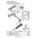
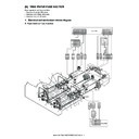
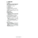
2. Operational descriptions
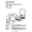
This machine employs the reduction optical type line CCD for scan
resolution in the main scanning direction. Scan resoultion is 600
DPI in the main scan direction and 300 DPI in the sub scan direc-
tion. Total of 7400 pixels.
Scanning is performed by moving mirror unit 1 and 2 in a sequen-
tial manner to scan the document.
Light reflected from the document to each mirror projects the image
onto the CCD after its been reduced by the lens.
The CCD converts the optical energy into electrical energy (ana-
log) (Photo electric conversion).
The image signal converted into electric energy (analog signal) is
converted on the AFE PWB into a digital signal.
Image processes such as white balance, shading correction are
performed on the SCNCNT PWB. The image signal is then sent to
the MFP control PWB.
In the MFP control PWB, image process is performed according to
the setting condition of the operation panel selected by the end
user EX reduction, enlargement etc. etc..
The image data is converted into video signal and sent to the PCU
then to the LSU (Laser Scan Unit).
In the LSU, the VIDEO signal is converted into laser beams, which
are radiated onto the drum.
The carriage scan speed is as follow.
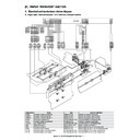
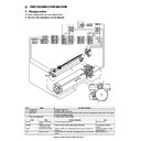
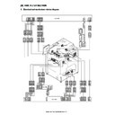
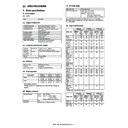
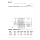
3. Disassembly and assembly
A. Scanner unit
SEL_IN 6
Sub scanning document size sensor
Reflectin type
Detects the sub scanning document size.
SEL_IN 7
Sub scanning document size sensor
Reflectin type
Detects the sub scanning document size.
SEL_IN 8
Sub scanning document size sensor
Reflectin type
Detects the sub scanning document size.
TH_CL
CL thermistor PWB
Scanner copy lamp temperature detection.
CLFM
Copy lamp cooling fan
Fan motor
Cools the copy lamp.
CCDFM
CCD coolong fan
Fan motor
Cools the CCD and the CL inverter.
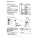
No.
Name
Function / Operation
1
CCD PWB
The Document image is scanned and is converted into a analog signal by the CCD.
2
CL inverter PWB
Inverter for lighting the scanner copy lamp.
3
AFE PWB
Image conversion scanned by CCD.
4
SCNCNT PWB
Controls the scanner.
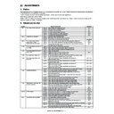
Signal name
Name
Type
Function / Operation
High speed mode
600dpi
✕ 300dpi
25 - 99%
600mm/s
100%
600mm/s
101 - 200%
600mm/s
201 - 400%
150mm/s
Unit
Parts
Page
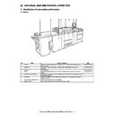
Scanner unit
A
Scanner lamp
D - 3/ a
B
Sub scanning document size
sensor
sensor
D - 5/ b
C
Main scanning document size
sensor
sensor
D
CL inverter PWB
D - 5/ c
E
AFE PWB
F
CCD cooling fan
G
CCD unit
H
SCN-Mother PWB
D - 6/ d
I
SCN-Flash PWB
D - 7/e
J
SCNCNT PWB
K
Scanner home position sensor
D - 8/ f
L
Scanner motor
D - 8/ g
M
Copy lamp cooling fan
D - 8/ h
N
CL Thermistor PWB
D - 8/ i
O
Scanner dehumidifying heater
D - 8/ j
C
N
I
O
J
K
M B
H
L
B
D
F
E
G
A
MX-M1100 SCANNER SECTION D – 3
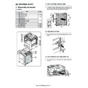
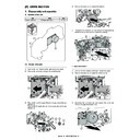
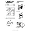
(1) Scanner unit
1)
Remove the DSPF unit.
2)
Remove the upper cabinet rear cover and the upper cabinet
rear.
rear.
3)
Remove the upper cabinet left, the upper cabinet right, the
upper cabinet front cover right, the upper cabinet front cover
left and the upper cabinet front.
upper cabinet front cover right, the upper cabinet front cover
left and the upper cabinet front.
4)
Disconnect the connector (a), and remove the screw (b).
Remove the fan duct unit (c).
Remove the fan duct unit (c).
5)
Disconnect the connector (a). Remove the screw (b), and pull
out the SCNCNT PWB mounting plate (c).
out the SCNCNT PWB mounting plate (c).
6)
Remove the table glass (a).
7)
Disconnect the connector (a), and remove the screw (b).
8)
Remove the scanner unit (a).
* When installing, be careful not to bring the scanner home
* When installing, be careful not to bring the scanner home
position sensor (b) and the rail collar (c) of the scanner unit
into contact with the machine.
into contact with the machine.
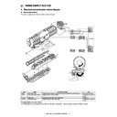
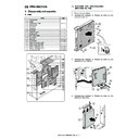
a. Scanner lamp
1)
Open the DSPF unit (a).
a
a
a
c
b
b
a
a
b
c
a
b
b
b
b
a
a
b
c
c
c
c
a
MX-M1100 SCANNER SECTION D – 4
2)
Remove the screw (a). Remove the table glass holder (b) and
the table glass (c).
the table glass (c).
3)
Remove the screw (a), and remove the SPF glass (b).
4)
Shift the lamp unit (a) to the right, and remove the screw (b).
5)
Disconnect the connector (a). Remove the scanner lamp (b).
6)
Cut the snap band (a), and remove the fixing material (c) from
the scanner lamp (b).
* When attaching, fix it with the snap band.
the scanner lamp (b).
* When attaching, fix it with the snap band.
* Installation of the scanner lamp.
a)
Install the scanner lamp. Pass the harness (a) through
the guide, then shift the lamp unit (b) to the left edge.
the guide, then shift the lamp unit (b) to the left edge.
b)
Slightly pull the harness (a), and put a mark (b) with a
pen.
pen.
a
b
c
a
b
a
b
b
a
b
c
b
a
a
b
a
b

