Read Sharp MX-M700U (serv.man34) Technical Bulletin online
Sharp Electronics (UK) Ltd., Document Systems Support
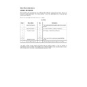
Ref: ARE971 NEW SERVICE PARTS FOR THE
SADDLE-STITCH FINISHER EJECTION TRAYS
SADDLE-STITCH FINISHER EJECTION TRAYS
1.Model Name:
AR-F16 (Options for MX-M550/M620/M700, AR-M550/620/700)
MX-FN16 (Options for MX-M623 /M753)
2.General:
When performing saddle-stitching, the numbers booklets that the ejection tray will hold is
limited, from 10 to 25.
limited, from 10 to 25.
Due to this, when copying from 10 to more than 25, the copy paper must be periodically
removed from the saddle ejection tray.Now, in response to requests from the market, we have
setup service parts so that the copy paper does not have to be periodically removed when copying
from 10 to 25 or more.
Furthermore, with this service, the saddle can be removed to allow for the copies to be ejected
directly onto the floor. This can let you use an alternative tray (such as a box with a size similar
to the copy paper).
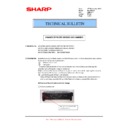
The mounting method for the supported service parts is on the attached pages.
- Service parts (Saddle frame cover)
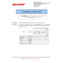
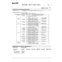
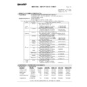
3.Parts Action:
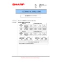
Ref.
No.
Model
name
Version P/G No.
Current parts
New parts
Price
rank
Q'ty
Parts name
Effective
time
Inter-
change
-
ability
Parts code
Parts code
1
AR-F16
ALL
---
---
PCOVP2389FCZZ
AZ
1
SADDLE FRAME
COVER
COVER
---
---
MX-FN16
<Interchange>
1. Interchangeable.
4. Not interchangeable.
2. Current type can be used in place of new type.
New type cannot be used in place of current type.
5. Interchangeable if replaced with same types of
related parts in use.
3. Current type cannot be used in place of new type.
New type can be used in place of current type.
6. Others.
Parts marked with "
" is important for maintaining the safety of the set. Be sure to replace these parts with
specified ones for maintaining the safety and performance of the set.
TECHNICAL BULLETIN
Date:
4
th
July 2010
Model:
AR-F16 (Options for AR/MX-M550/M620/M700,
MX-FN16 (Options for MX-M623/M753)
MX-FN16 (Options for MX-M623/M753)
Ref.: ARE971
Colour:
White
Page:
1 of 6
Sharp Electronics (UK) Ltd., Document Systems Support
How to Mount the Saddle Frame Cover
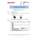
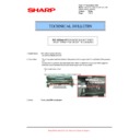
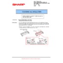
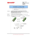
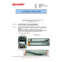
(1) Open the saddle ejection frame, press on the inside of the saddle ejection tray revolving support to
remove the ejection tray.
(2) Remove 1 screw from the saddle ejection tray back, and then remove the sensor cover.
(3) Remove the ejection tray sensor and the harness from the saddle ejection tray.
Sharp Electronics (UK) Ltd., Document Systems Support
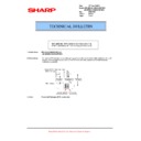
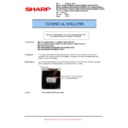
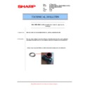
(4) Remove bundle fastener [1], bundle fastener [2] and bundle fastener [3] from the harness.
Remove bundle fastener [1] from the plate.
(5) Remove the ejection sensor connected to the harness on the inside of the ejection frame from the
relay connector.
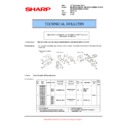
(6) Open the saddle ejection frame, remove the axel in the direction indicated by the arrow, and remove
the saddle ejection frame by pulling it toward yourself.
Sharp Electronics (UK) Ltd., Document Systems Support
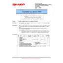
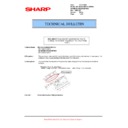
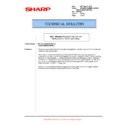
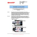
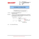
(7) Secure the relay connector (previously removed) harness through the wire hooks on the inside of the
saddle ejection frame (2 hooks) and with the securing rib.
(8) Pull the ejection sensor harness that is coming through the hole and connect it with the relay
connector.
(9) Bundle the sensor harness that was removed from the ejection tray and secure with bundle fastener
[2] and bundle fastener [3].
At this time, if the photo sensor becomes shielded from light, it will malfunction. Be sure to leave
about 30 mm from the harness bundle.
At this time, if the photo sensor becomes shielded from light, it will malfunction. Be sure to leave
about 30 mm from the harness bundle.

