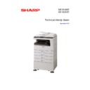
Read Sharp MX-M200D / MX-M200DK (serv.man2) Service Manual online
Parts marked with “
“ are important for maintaining the safety of the set.
Be sure to replace these parts with specified ones for maintaining the safety and performance of the set.
SERVICE MANUAL
SHARP CORPORATION
DIGITAL
MULTIFUNCTIONAL
SYSTEM
MULTIFUNCTIONAL
SYSTEM
MX-M200D
MX-M200DK
MX-M160D
MX-M160DK
MX-M160
MX-M200DK
MX-M160D
MX-M160DK
MX-M160
As for the content of the MX-M200DK/MX-M160DK, refer to the
content of the MX-M200D/MX-M160D as long as there is no
proviso.
content of the MX-M200D/MX-M160D as long as there is no
proviso.
CODE : 00ZMXM200DS1E
MX-M200D
MX-M160D
MX-M160
MX-M160
[ 1 ] GENERAL . . . . . . . . . . . . . . . . . . . . . . . . . . . . . . . . . . . . . . . . . 1 - 1
[ 2 ] CONFIGURATION. . . . . . . . . . . . . . . . . . . . . . . . . . . . . . . . . . . 2 - 1
[ 3 ] SPECIFICATIONS. . . . . . . . . . . . . . . . . . . . . . . . . . . . . . . . . . . 3 - 1
[ 4 ] CONSUMABLE PARTS. . . . . . . . . . . . . . . . . . . . . . . . . . . . . . . 4 - 1
[ 5 ] EXTERNAL VIEWS AND INTERNAL STRUCTURES . . . . . . . 5 - 1
[ 6 ] ADJUSTMENTS . . . . . . . . . . . . . . . . . . . . . . . . . . . . . . . . . . . . 6 - 1
[ 7 ] SIMULATIONS . . . . . . . . . . . . . . . . . . . . . . . . . . . . . . . . . . . . . 7 - 1
[ 8 ] USER PROGRAMS . . . . . . . . . . . . . . . . . . . . . . . . . . . . . . . . . 8 - 1
[ 9 ] TROUBLE CODE LIST . . . . . . . . . . . . . . . . . . . . . . . . . . . . . . . 9 - 1
[10] MAINTENANCE . . . . . . . . . . . . . . . . . . . . . . . . . . . . . . . . . . . 10 - 1
[11] DISASSEMBLY AND ASSEMBLY . . . . . . . . . . . . . . . . . . . . . . 11 - 1
[12] FLASH ROM VERSION UP PROCEDURE . . . . . . . . . . . . . . 12 - 1
[13] ELECTRICAL SECTION . . . . . . . . . . . . . . . . . . . . . . . . . . . . . 13 - 1
CONTENTS
MODEL
[1] GENERAL
1. Note for servicing . . . . . . . . . . . . . . . . . . . . . . . . . . 1-1
[2] CONFIGURATION
1. System Configurations . . . . . . . . . . . . . . . . . . . . . . 2-1
2. Machine configuration . . . . . . . . . . . . . . . . . . . . . . . 2-1
3. Option list . . . . . . . . . . . . . . . . . . . . . . . . . . . . . . . . 2-2
[3] SPECIFICATIONS
1. Copy mode . . . . . . . . . . . . . . . . . . . . . . . . . . . . . . . 3-1
[4] CONSUMABLE PARTS
1, Supply system table . . . . . . . . . . . . . . . . . . . . . . . . 4-1
2. Environmental conditions . . . . . . . . . . . . . . . . . . . . 4-2
3. Production number identification . . . . . . . . . . . . . . . 4-2
[5] EXTERNAL VIEWS AND INTERNAL STRUCTURES
1. Appearance . . . . . . . . . . . . . . . . . . . . . . . . . . . . . . . 5-1
2. Internal . . . . . . . . . . . . . . . . . . . . . . . . . . . . . . . . . . 5-2
3. Operation Section . . . . . . . . . . . . . . . . . . . . . . . . . . 5-3
4. Motor, solenoid, clutch. . . . . . . . . . . . . . . . . . . . . . . 5-4
5. Sensor, switch . . . . . . . . . . . . . . . . . . . . . . . . . . . . . 5-5
6. PWB unit . . . . . . . . . . . . . . . . . . . . . . . . . . . . . . . . . 5-6
7. Cross sectional view . . . . . . . . . . . . . . . . . . . . . . . . 5-7
[6] ADJUSTMENTS
1. Adjustment item list . . . . . . . . . . . . . . . . . . . . . . . . . 6-1
2. Copier adjustment . . . . . . . . . . . . . . . . . . . . . . . . . . 6-1
[7] SIMULATIONS
1. Entering the simulation mode . . . . . . . . . . . . . . . . . 7-1
2. Canceling the simulation mode . . . . . . . . . . . . . . . . 7-1
3. List of simulations . . . . . . . . . . . . . . . . . . . . . . . . . . 7-1
4. Contents of simulations . . . . . . . . . . . . . . . . . . . . . . 7-3
[8] SYSTEM SETTINGS
1. List of user programs. . . . . . . . . . . . . . . . . . . . . . . . 8-1
2. Using the system settings . . . . . . . . . . . . . . . . . . . . 8-2
[9] TROUBLE CODE LIST
1. Trouble code list . . . . . . . . . . . . . . . . . . . . . . . . . . . 9-1
2. Details of trouble codes. . . . . . . . . . . . . . . . . . . . . . 9-1
[10] MAINTENANCE
1. Maintenance table . . . . . . . . . . . . . . . . . . . . . . . . . 10-1
2. Maintenance display system . . . . . . . . . . . . . . . . . 10-2
3. Note for replacement of consumable parts . . . . . . 10-2
[11] DISASSEMBLY AND ASSEMBLY
1. High voltage section/Duplex transport section . . . 11-1
2. Optical section. . . . . . . . . . . . . . . . . . . . . . . . . . . . 11-2
3. Fusing section . . . . . . . . . . . . . . . . . . . . . . . . . . . . 11-4
4. Paper exit section . . . . . . . . . . . . . . . . . . . . . . . . . 11-6
5. MCU . . . . . . . . . . . . . . . . . . . . . . . . . . . . . . . . . . . 11-8
6. Optical frame unit . . . . . . . . . . . . . . . . . . . . . . . . . 11-9
7. LSU . . . . . . . . . . . . . . . . . . . . . . . . . . . . . . . . . . . . 11-9
8. Tray paper feed section/Paper transport section. . 11-9
9. Bypass tray section . . . . . . . . . . . . . . . . . . . . . . 11-11
10.Power section . . . . . . . . . . . . . . . . . . . . . . . . . . . 11-13
11.Developing section . . . . . . . . . . . . . . . . . . . . . . . 11-14
12.Process section . . . . . . . . . . . . . . . . . . . . . . . . . . 11-15
13.Others
13.Others
. . . . . . . . . . . . . . . . . . . . . . . . . . . . . . . . . 11-15
[12] FLASH ROM VERSION UP PROCEDURE
1. Preparation . . . . . . . . . . . . . . . . . . . . . . . . . . . . . . .12-1
2. Installation procedure . . . . . . . . . . . . . . . . . . . . . .12-1
3. Firmware update procedure . . . . . . . . . . . . . . . . . .12-2
[13] ELECTRICAL SECTION
1. Block diagram. . . . . . . . . . . . . . . . . . . . . . . . . . . . .13-1
2, Actual wiring diagram . . . . . . . . . . . . . . . . . . . . . . .13-2
3. Signal name list . . . . . . . . . . . . . . . . . . . . . . . . . . .13-9
LEAD-FREE SOLDER
CONTENTS
This product is a class 1 laser product that complies with 21CFR 1040.10 and 1040.11 of the CDRH standard and IEC60825-1 Edition 1.2-2001.
1) When a problem in the laser optical unit has occurred, the whole optical unit must be exchanged as a unit, not as individual parts.
3)
2) Do not look into the machine with the main switch turned on after removing the developer unit, toner cartridge, and drum cartridge.
Do not look into the laser beam exposure slit of the laser optical unit with the connector connected when removing and installing the optical
system.
system.
4) The middle frame contains the safety interlock switch.
Do not defeat the safety interlock by inserting wedges or other items into the switch slot.
The following cautions must be observed to avoid exposure of the laser beam to your eyes at the time of servicing.
This laser radiation is not a danger to the skin, but when an exact focusing of the laser beam is achieved on the eye's retina, there is the danger of
spot damage to the retina.
spot damage to the retina.
This means that this machine does not produce hazardous laser radiation. The use of controls, adjustments or performance of procedures other
than those specified herein may result in hazardous radiation exposure.
than those specified herein may result in hazardous radiation exposure.
CAUTION
Warning:
This is a Cla
Disconnect the AC cord before servicing the unit.
LASER WAVE - LENGTH: 785 nm + 10 nm/ 15 nm
Pulse times : (8.141 s 0.1 s/7 mm
Output power : 0.14 mW 0.22 mW
Pulse times : (8.141 s 0.1 s/7 mm
Output power : 0.14 mW 0.22 mW
ss A product. In a domestic environment this product may cause radio interference in which case
the user may be required to take adequate measures.
LUOKAN 1 LASERLAITE
KLASS 1 LASERAPPARAT
MX-M160 GENERAL 1-1
[1] GENERAL
1. Note for servicing
Pictogram
The label (
) in the fusing area of the machine indicates the
following:
: Caution, risk of danger
: Caution, hot surface
: Caution, hot surface
A. Warning for servicing
•The fusing area is hot. Exercise care in this area when removing misfed
paper.
•Do not look directly at the light source. Doing so may damage your eyes.
B. Cautions for servicing
•Do not switch the machine rapidly on and off. After turning the machine
off, wait 10 to 15 seconds before turning it back on.
•Machine power must be turned off before installing any supplies.
•Place the machine on a firm, level surface.
•Do not install the machine in a humid or dusty location.
•When the machine is not used for a long time, for example, during
•Place the machine on a firm, level surface.
•Do not install the machine in a humid or dusty location.
•When the machine is not used for a long time, for example, during
prolonged holidays, turn the power switch off and remove the power
cord from the outlet.
cord from the outlet.
•When moving the machine, be sure to turn the power switch off and
remove the power cord from the outlet.
•Do not cover the machine with a dust cover, cloth or plastic film while the
power is on. Doing so may prevent heat dissipation, damaging the
machine.
machine.
•Use of controls or adjustments or performance of procedures other than
those specified herein may result in hazardous laser radiation
exposure.
exposure.
•The socket-outlet shall be installed near the machine and shall be easily
accessible.
C. Note for installation place
Improper installation may damage the machine. Please note the
following during initial installation and whenever the machine is moved.
following during initial installation and whenever the machine is moved.
Caution : If the machine is moved from a cool place to a warm place,
condensation may form inside the machine. Operation in this
condition will cause poor copy quality and malfunctions. Leave
the machine at room temperature for at least 2 hours before
use.
condition will cause poor copy quality and malfunctions. Leave
the machine at room temperature for at least 2 hours before
use.
Do not install your machine in areas that are:
•damp, humid, or very dusty
•poorly ventilated
•exposed to direct sunlight
•subject to extreme temperature or humidity changes, e.g., near an air
conditioner or heater.
The machine should be installed near an accessible power outlet for
easy connection and disconnection.
Be sure to connect the power cord only to a power outlet that meets the
specified voltage and current requirements. Also make certain the outlet
is properly grounded.
easy connection and disconnection.
Be sure to connect the power cord only to a power outlet that meets the
specified voltage and current requirements. Also make certain the outlet
is properly grounded.
Note : Connect the machine to a power outlet which is not used for other
electric appliances. If a lighting fixture is connected to the same
outlet, the light may flicker.
outlet, the light may flicker.
Be sure to allow the required space around the machine for servicing
and proper ventilation.
and proper ventilation.
20 cm
(8")
20 cm
(8")
20 cm (8")

