Read Sharp MX-LC13 (serv.man15) Technical Bulletin online
Sharp Electronics (UK) Ltd., Technical Services Group
CCE-1269
1. Model Name: MX-LC13 (Option for MX-6240N/7040N/6500N/7500N,MX-M904/M1054/M1204)
2. Description:
To improve the installation of the MX-LC13 to the above listed models the following
changes have been implemented:
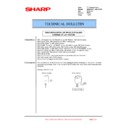
*Positioning Plated F/R (NO 7 & 8) have been eliminated from the accessories
To support this change the MX-RB14 to include the Joint plate at the time of shipment
Due to the changes above, the installation procedure has also been changed so please
refer to the latest Installation Manual for models below:
Eliminated from July 2013
[Positioning plate F]
[Positioning plate R]
<Latest version of Installation Manual>
MX-M904/M1054/M1204 : 00ZMXM1204I6E (Revised in January 2014)
MX-6240N/7040N : 00ZMX7040/I8E (Revised in January 2014)
MX-6500N/7500N : 00ZMX7500/I3E (Revised in January 2014)
MX-M904/M1054/M1204 : 00ZMXM1204I6E (Revised in January 2014)
MX-6240N/7040N : 00ZMX7040/I8E (Revised in January 2014)
MX-6500N/7500N : 00ZMX7500/I3E (Revised in January 2014)
IMPROVEMENT OF INSTALLATION
SUITABILITY OF MX-LC13
TECHNICAL BULLETIN
Date:
29
th
April 2016
Model:
MX-LC13 – MX-LC13N
Ref.:
CCE-1269
Colour:
White
Page:
1 of 1
2/2
<Notes when installing MX-LC13 to MX-6240N/7040N/6500N/7500N>
When installing MX-LC13 to MX-6240N/7040N/6500N/7500N, the connection with MX-RB14 is
required.
Along with this change, the necessity of the installation work/supplied parts varies depending on
the combination of current/new packing No. of MX-LC13 and packing No. of MX-RB14 so please
see Combination table for installation procedure on the following page and take action
accordingly.
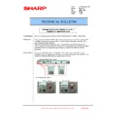
- Combination table for installation procedure
Main unit
MX-LC13
MX-RB14
Positioning
plate F/R
Joint plate
lower F/R
Installation
procedure
MX-M904
MX-M1054
MX-M1204
MX-M1054
MX-M1204
A35 or A25 (Current)
-
Necessary
Necessary
Installation1
A46 or A36 (New)
-
Unnecessary
Necessary
Installation2
MX-6240N
MX-7040N
MX-6500N
MX-7500N
MX-7040N
MX-6500N
MX-7500N
A35 or A25 (Current)
A10(Current)
Necessary
Necessary
Installation1
A46 or A36 (New)
A10(Current)
Unnecessary
Necessary
Installation2
A35 or A25 (Current)
A20 (New)
Necessary
Unnecessary*
Installation3
A46 or A36 (New)
A20 (New)
Unnecessary
Unnecessary*
Installation4
(*) Already installed to MX-RB14 at the time of factory shipment
- Identification method of production month: Please check the label affixed to the packing case.
Model
Packing control No.
Production period
MX-LC13
A35(120Vseries)
Before June 2013
A25(200Vseries)
Before June 2013
A46(120Vseries)
After July 2013
A36(200Vseries)
After July 2013
MX-RB14
(Option for MX-6240N/7040N/6500N/7500N-Only)
(Option for MX-6240N/7040N/6500N/7500N-Only)
A00/A10
Before June 2013
A20
After August 2013
A46
MX-M1204 MX-LC13 (LARGE CAPACITY TRAYS) 8 – 1
MX-M1204
Service Manual
[8] MX-LC13 (LARGE CAPACITY TRAYS)
1. Unpacking
A. Remove the large capacity trays
1) Remove the machine from the palette with a forklift or a slope
(DKIT-0367FCZZ).
NOTE: When using a forklift, raise the casters to the top in
order not to break them.
B. Packed items check
*1: Not packed after July / 2013 production
*2: Packed number was changed after July / 2013 production
*2: Packed number was changed after July / 2013 production
2. Unit production month check
A. Unit production month check
Check the label on the carton box as the figure below.
Before June 2013 production: Go to [3. Installation 1]
120V series: Less than A35
200V series: Less than A25
After July 2013 production: Go to [4. Installation 2]
120V series: More than A46
200V series: More than A36
Before June 2013 production: Go to [3. Installation 1]
120V series: Less than A35
200V series: Less than A25
After July 2013 production: Go to [4. Installation 2]
120V series: More than A46
200V series: More than A36
3. Installation1
NOTE: Before installation, be sure to turn both the operation and
main power switches off and disconnect the power plug
from the power outlet. Make double sure that the data lamp
on the operation panel does not light up or blink when per-
forming installation.
from the power outlet. Make double sure that the data lamp
on the operation panel does not light up or blink when per-
forming installation.
NOTE: When installing this machine in a place of low atmospheric
pressure, check and conform to the adjustment contents in
the MX-LC13 Service Manual.
the MX-LC13 Service Manual.
A. Release the lock
1)
Draw out the second tray from the unit.
Push the button of the bottom side of the unit to unlock the
tray, and then slowly pull out the tray until it stops.
Push the button of the bottom side of the unit to unlock the
tray, and then slowly pull out the tray until it stops.
2)
Remove 3 screws from the tray.
3)
Slowly insert the tray to the original position.
No.
Name
Quantity
1
LCT connecting plate F
1
2
LCT connecting plate R
1
3
Height adjustment plate
4
4
Screw (S-tight, M4 x 8)
11 to 8 *2
5
Power cable
1
6
Connecting plate upper
2
7
Positioning plate F *1
1
8
Positioning plate R *1
1
9
Connecting plate lower F
1
10
Connecting plate lower R
1
11
Screw (Hex washer S-tight M4 x 18)
4
12
L-shape driver
1
TopPage
4
: ‘14/Jan
4
MX-M1204 MX-LC13 (LARGE CAPACITY TRAYS) 8 – 2
B. Install to the machine
1) Attach the LCT connecting plate to the large capacity trays
with screws (Packed items No. 4 S-tight, M4 x 8).
MEMO: The reference label is attached to the plate. Attach it
so that the label can be seen from the outside.
MEMO: The reference label is attached to the plate. Attach it
so that the label can be seen from the outside.
2) Attach the connection plates (F/R) to the machine with screws
(Packed items No. 4 S-tight, M4 x 8).
3) Fix the upper mounting plates to the main unit with the screws
(Packed items No. 11 Hex washer S-tight M4 x 18).
4)
Joint the LCT connecting plates (F/R) fixed to MX-LC13 and
the connecting plates (F/R) fixed to the main unit.
the connecting plates (F/R) fixed to the main unit.
5)
Ensure even clearance of the upper section by pushing the
MX-LC13.
MX-LC13.
6)
Open the front door of MX-LC13 and remove the screw and
remove the lower cabinet.
remove the lower cabinet.
TopPage
4
: ‘14/Jan
4

