|
|
MX-C250 MX-C250E MX-C250F MX-C250FE MX-C250FR MX-C300F MX-C300W MX-C300WE MX-C300A MX-C300WR (serv.man6)
Service Manual (Revised May 2016).
Service Manual
|
127
|
29.56 MB
|
|
|
MX-C250 MX-C250E MX-C250F MX-C250FE MX-C250FR MX-C300F MX-C300W MX-C300WE MX-C300A MX-C300WR (serv.man7)
Installation Manual (Revised July 2014).
Service Manual
|
20
|
2.2 MB
|
|
|
MX-C250 MX-C250E MX-C250F MX-C250FE MX-C250FR MX-C300F MX-C300W MX-C300WE MX-C300A MX-C300WR (serv.man8)
Circuit Diagrams
Service Manual
|
99
|
3.58 MB
|
|
|
MX-C250 MX-C250E MX-C250F MX-C250FE MX-C250FR MX-C300F MX-C300W MX-C300WE MX-C300A MX-C300WR (serv.man9)
MX-CS11 Service Manual
Service Manual
|
13
|
1.5 MB
|
|
|
MX-C250 MX-C250E MX-C250F MX-C250FE MX-C250FR MX-C300F MX-C300W MX-C300WE MX-C300A MX-C300WR (serv.man12)
Start Guide
User Guide / Operation Manual
|
8
|
1.08 MB
|
|
|
MX-C250 MX-C250E MX-C250F MX-C250FE MX-C250FR MX-C300F MX-C300W MX-C300WE MX-C300A MX-C300WR (serv.man13)
Software Set-up Guide
User Guide / Operation Manual
|
44
|
1.71 MB
|
|
|
MX-C250 MX-C250E MX-C250F MX-C250FE MX-C250FR MX-C300F MX-C300W MX-C300WE MX-C300A MX-C300WR (serv.man14)
Operation Manual
User Guide / Operation Manual
|
127
|
24.5 MB
|
|
|
MX-C250 MX-C250E MX-C250F MX-C250FE MX-C250FR MX-C300F MX-C300W MX-C300WE MX-C300A MX-C300WR (serv.man15)
Revised Installation Manual
User Guide / Operation Manual
|
19
|
2.18 MB
|
|
|
MX-C250 MX-C250E MX-C250F MX-C250FE MX-C250FR MX-C300F MX-C300W MX-C300WE MX-C300A MX-C300WR (serv.man10)
Parts Guide (Revised June 2016).
Parts Guide
|
104
|
14.05 MB
|
|
|
MX-C250 MX-C250E MX-C250F MX-C250FE MX-C250FR MX-C300F MX-C300W MX-C300WE MX-C300A MX-C300WR (serv.man11)
PWB Parts Guide (Revised June 2014).
Parts Guide
|
40
|
587.89 KB
|
|
|
MX-C250 MX-C250E MX-C250F MX-C250FE MX-C250FR MX-C300F MX-C300W MX-C300WE MX-C300A MX-C300WR (serv.man4)
CCE829R5 PROCEDURES FOR USING SERVICE PERSONNEL-ORIENTED FUNCTIONS INSTALLED IN SHARP REMOTTE DEVICE MANAGER
Specification
|
18
|
2.11 MB
|
|
|
MX-C250 MX-C250E MX-C250F MX-C250FE MX-C250FR MX-C300F MX-C300W MX-C300WE MX-C300A MX-C300WR (serv.man5)
Specifications
Specification
|
8
|
814.15 KB
|
|
|
MX-C250 MX-C250E MX-C250F MX-C250FE MX-C250FR MX-C300F MX-C300W MX-C300WE MX-C300A MX-C300WR (serv.man53)
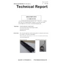
CCE1348 REMOVAL OF SHEETS ATTACHED TO 2ND TRANSFER UNIT
Technical Bulletin
|
2
|
121.12 KB
|
|
|
MX-C250 MX-C250E MX-C250F MX-C250FE MX-C250FR MX-C300F MX-C300W MX-C300WE MX-C300A MX-C300WR (serv.man59)
ROM UPGRADE ... (7).
Technical Bulletin
|
2
|
38.36 KB
|
|
|
MX-C250 MX-C250E MX-C250F MX-C250FE MX-C250FR MX-C300F MX-C300W MX-C300WE MX-C300A MX-C300WR (serv.man54)
CCE1349 REMOVAL OF THERMAL SHEET ON MFPC FIXING PLATE
Technical Bulletin
|
1
|
122.04 KB
|
|
|
MX-C250 MX-C250E MX-C250F MX-C250FE MX-C250FR MX-C300F MX-C300W MX-C300WE MX-C300A MX-C300WR (serv.man55)
CCE 1341 ROM UPGRADE 02.05.E1.00
Technical Bulletin
|
3
|
61.05 KB
|
|
|
MX-C250 MX-C250E MX-C250F MX-C250FE MX-C250FR MX-C300F MX-C300W MX-C300WE MX-C300A MX-C300WR (serv.man56)
CCE 1346 COUNTERMEASURE FOR NOISE FROM PAPER FEEDING ROLLER
Technical Bulletin
|
2
|
160.6 KB
|
|
|
MX-C250 MX-C250E MX-C250F MX-C250FE MX-C250FR MX-C300F MX-C300W MX-C300WE MX-C300A MX-C300WR (serv.man57)
CCE1338 CHANGE OF SERVICE PARTS CONFIGURATION-OPERATION PANEL UNIT SECTION
Technical Bulletin
|
3
|
235.88 KB
|
|
|
MX-C250 MX-C250E MX-C250F MX-C250FE MX-C250FR MX-C300F MX-C300W MX-C300WE MX-C300A MX-C300WR (serv.man58)
CCE1330 SET UP OF NEW SERVICE PARTS DELIVERY AUXILIARY GUIDE
Technical Bulletin
|
3
|
412.09 KB
|
|
|
MX-C250 MX-C250E MX-C250F MX-C250FE MX-C250FR MX-C300F MX-C300W MX-C300WE MX-C300A MX-C300WR (serv.man67)
CCE-1231 PRECAUTION FOR REMOVING OR REPLACING THE FFC
Technical Bulletin
|
4
|
1.11 MB
|
|
|
MX-C250 MX-C250E MX-C250F MX-C250FE MX-C250FR MX-C300F MX-C300W MX-C300WE MX-C300A MX-C300WR (serv.man52)
Countermeasures against contamination of paper surface.
Technical Bulletin
|
2
|
24.64 KB
|
|
|
MX-C250 MX-C250E MX-C250F MX-C250FE MX-C250FR MX-C300F MX-C300W MX-C300WE MX-C300A MX-C300WR (serv.man51)
CCE-1350 REMEDY FOR NOISE GENERATED WHILE FEEDING PAPER FROM MULTI MANUAL PAPER FEEDING UNIT
Technical Bulletin
|
2
|
86.34 KB
|
|
|
MX-C250 MX-C250E MX-C250F MX-C250FE MX-C250FR MX-C300F MX-C300W MX-C300WE MX-C300A MX-C300WR (serv.man50)
CCE-1366 REDUCTION OF A FERRITE CORE (BUNDLED WITH MAIN UNIT)
Technical Bulletin
|
1
|
90.85 KB
|
|
|
MX-C250 MX-C250E MX-C250F MX-C250FE MX-C250FR MX-C300F MX-C300W MX-C300WE MX-C300A MX-C300WR (serv.man49)
CCE-1363 IMPROVEMENT FOR H3 TROUBLE CODE ETC.
Technical Bulletin
|
3
|
364.77 KB
|
|
|
MX-C250 MX-C250E MX-C250F MX-C250FE MX-C250FR MX-C300F MX-C300W MX-C300WE MX-C300A MX-C300WR (serv.man48)
CCE-1391 MODIFICATION OF NOISE GENERATED WHILE FEEDING ORIGINAL
Technical Bulletin
|
3
|
225.39 KB
|
|
|
MX-C250 MX-C250E MX-C250F MX-C250FE MX-C250FR MX-C300F MX-C300W MX-C300WE MX-C300A MX-C300WR (serv.man47)
IMPORTANT Handling of EEPROM's.
Technical Bulletin
|
5
|
203.32 KB
|
|
|
MX-C250 MX-C250E MX-C250F MX-C250FE MX-C250FR MX-C300F MX-C300W MX-C300WE MX-C300A MX-C300WR (serv.man46)
CCE1440 ENHANCEMENT OF OPERABILITY IN OPENING CLOSING MULTI MANUAL PAPER FEEDING UNIT
Technical Bulletin
|
2
|
156.98 KB
|
|
|
MX-C250 MX-C250E MX-C250F MX-C250FE MX-C250FR MX-C300F MX-C300W MX-C300WE MX-C300A MX-C300WR (serv.man45)
CCE 1460 CHANGE IN COLOR OF BELT COUPLING JOINT
Technical Bulletin
|
2
|
169.78 KB
|
|
|
MX-C250 MX-C250E MX-C250F MX-C250FE MX-C250FR MX-C300F MX-C300W MX-C300WE MX-C300A MX-C300WR (serv.man60)
CCE-1317 OPEN SSL VULNERABILITY FIRMWARE RELEASE FOR FIELD SUPPORT VERSION
Technical Bulletin
|
4
|
242.22 KB
|
|
|
MX-C250 MX-C250E MX-C250F MX-C250FE MX-C250FR MX-C300F MX-C300W MX-C300WE MX-C300A MX-C300WR (serv.man62)
Procedure for using Service Personnel Oriented Functions in Sharp Remote Device Manager.
Technical Bulletin
|
18
|
2.11 MB
|
|
|
MX-C250 MX-C250E MX-C250F MX-C250FE MX-C250FR MX-C300F MX-C300W MX-C300WE MX-C300A MX-C300WR (serv.man63)
CCE-1281 SOLUTION FOR PAPER JAM (AT SPPD1_NR ETC.) DUE TO THE WARPING OF REVERSE SELF WEIGHT GATE
Technical Bulletin
|
2
|
134.34 KB
|
|
|
MX-C250 MX-C250E MX-C250F MX-C250FE MX-C250FR MX-C300F MX-C300W MX-C300WE MX-C300A MX-C300WR (serv.man64)
CCE-1260 COUNTERMEASURE FOR INCONSISTENCIES IN PITCH BY CHANGING TYPE OF GEAR OF MAIN DRIVE UNIT
Technical Bulletin
|
2
|
102.4 KB
|
|
|
MX-C250 MX-C250E MX-C250F MX-C250FE MX-C250FR MX-C300F MX-C300W MX-C300WE MX-C300A MX-C300WR (serv.man65)
CCE-1259 NOISE FROM MAIN DRIVE UNIT
Technical Bulletin
|
2
|
284.82 KB
|
|
|
MX-C250 MX-C250E MX-C250F MX-C250FE MX-C250FR MX-C300F MX-C300W MX-C300WE MX-C300A MX-C300WR (serv.man66)
CCE-1258 OPERATING SOUND OF FUSING COOLING FAN IN PRE-HEAT MODE
Technical Bulletin
|
1
|
14.55 KB
|
|
|
MX-C250 MX-C250E MX-C250F MX-C250FE MX-C250FR MX-C300F MX-C300W MX-C300WE MX-C300A MX-C300WR (serv.man38)
CCE1501 CHANGE IN FERRITE CORE FOR FAX LINE CABLE
Technical Bulletin
|
2
|
273.37 KB
|
|
|
MX-C250 MX-C250E MX-C250F MX-C250FE MX-C250FR MX-C300F MX-C300W MX-C300WE MX-C300A MX-C300WR (serv.man68)
CCE1252 OPERATING SOUND REDUCTION DURING MANUAL PAPER FEEDING
Technical Bulletin
|
2
|
115.78 KB
|
|
|
MX-C250 MX-C250E MX-C250F MX-C250FE MX-C250FR MX-C300F MX-C300W MX-C300WE MX-C300A MX-C300WR (serv.man69)
CCE1249 IMPROVED DENSITY UNEVENNESS BY ADDING SPF RSPF REAR MYLAR
Technical Bulletin
|
2
|
202.64 KB
|
|
|
MX-C250 MX-C250E MX-C250F MX-C250FE MX-C250FR MX-C300F MX-C300W MX-C300WE MX-C300A MX-C300WR (serv.man70)
CCE1248 SHAPE CHANGE OF INTERIOR EXHAUST INTAKE DUCT COVER FOR PRODUCTIVITY IMPROVEMENT
Technical Bulletin
|
2
|
99.06 KB
|
|
|
MX-C250 MX-C250E MX-C250F MX-C250FE MX-C250FR MX-C300F MX-C300W MX-C300WE MX-C300A MX-C300WR (serv.man71)
CCE1246 MODIFICATION OF NOISE WHILE REVERSE GATE IS MOVING
Technical Bulletin
|
2
|
77.92 KB
|
|
|
MX-C250 MX-C250E MX-C250F MX-C250FE MX-C250FR MX-C300F MX-C300W MX-C300WE MX-C300A MX-C300WR (serv.man72)
CCE1245 IMPROVEMENT FOR SILENCING OF RSPF MOTOR NOISE
Technical Bulletin
|
2
|
245.39 KB
|
|
|
MX-C250 MX-C250E MX-C250F MX-C250FE MX-C250FR MX-C300F MX-C300W MX-C300WE MX-C300A MX-C300WR (serv.man73)
IMPROVEMENT FOR NOISE FROM RSPF UNIT
Technical Bulletin
|
1
|
47.04 KB
|
|
|
MX-C250 MX-C250E MX-C250F MX-C250FE MX-C250FR MX-C300F MX-C300W MX-C300WE MX-C300A MX-C300WR (serv.man74)
Bulletin for ROM Update 01.10.E1.00
Technical Bulletin
|
4
|
49.03 KB
|
|
|
MX-C250 MX-C250E MX-C250F MX-C250FE MX-C250FR MX-C300F MX-C300W MX-C300WE MX-C300A MX-C300WR (serv.man75)
PREVENTION OF L4-06 ERROR DUE TO THE DAMAGE ON 1TUD HARNESS
Technical Bulletin
|
2
|
197.44 KB
|
|
|
MX-C250 MX-C250E MX-C250F MX-C250FE MX-C250FR MX-C300F MX-C300W MX-C300WE MX-C300A MX-C300WR (serv.man29)
CCE-1759R SERVICE PARTS SETUP OF FUSING SECTION
Technical Bulletin
|
3
|
554.63 KB
|
|
|
MX-C250 MX-C250E MX-C250F MX-C250FE MX-C250FR MX-C300F MX-C300W MX-C300WE MX-C300A MX-C300WR (serv.man78)
Rom Upgrade Version 2 (Fax Ring Issue)
Technical Bulletin
|
1
|
18.45 KB
|
|
|
MX-C250 MX-C250E MX-C250F MX-C250FE MX-C250FR MX-C300F MX-C300W MX-C300WE MX-C300A MX-C300WR (serv.man77)
Fax Recieving Trouble
Technical Bulletin
|
1
|
100.81 KB
|
|
|
MX-C250 MX-C250E MX-C250F MX-C250FE MX-C250FR MX-C300F MX-C300W MX-C300WE MX-C300A MX-C300WR (serv.man76)
PREVENTION OF PAPER JAM AT FUSER DUE TO LEAD EDGE ADJUSTMENT
Technical Bulletin
|
2
|
24.42 KB
|
|
|
MX-C250 MX-C250E MX-C250F MX-C250FE MX-C250FR MX-C300F MX-C300W MX-C300WE MX-C300A MX-C300WR (serv.man28)
CCE-1804 DESIGN CHANGE OF RSPF ORIGINAL GUIDE
Technical Bulletin
|
2
|
217.83 KB
|
|
|
MX-C250 MX-C250E MX-C250F MX-C250FE MX-C250FR MX-C300F MX-C300W MX-C300WE MX-C300A MX-C300WR (serv.man44)
CCE-1463 COUNTERMEASURE FOR F3-22 TROUBLE DUE TO THE BREAKAGE OF 2CS SENSOR HARNESS
Technical Bulletin
|
2
|
199.1 KB
|
|
|
MX-C250 MX-C250E MX-C250F MX-C250FE MX-C250FR MX-C300F MX-C300W MX-C300WE MX-C300A MX-C300WR (serv.man30)
CCE-1712 CHANGE OF RSPF UNIT PAPER FEED SHAFT
Technical Bulletin
|
2
|
246.82 KB
|
|
|
MX-C250 MX-C250E MX-C250F MX-C250FE MX-C250FR MX-C300F MX-C300W MX-C300WE MX-C300A MX-C300WR (serv.man31)
CCE-1686 ENHANCEMENT OF PAPER TRAY INSERTION
Technical Bulletin
|
1
|
76.83 KB
|
|
|
MX-C250 MX-C250E MX-C250F MX-C250FE MX-C250FR MX-C300F MX-C300W MX-C300WE MX-C300A MX-C300WR (serv.man32)
CCE-1652 CHANGE IN DESIGN OF PAPER FEED SHAFT
Technical Bulletin
|
2
|
659.27 KB
|
|
|
MX-C250 MX-C250E MX-C250F MX-C250FE MX-C250FR MX-C300F MX-C300W MX-C300WE MX-C300A MX-C300WR (serv.man33)
CCE-1622 Reduction Of Noise Caused When Opening SPF
Technical Bulletin
|
2
|
413.51 KB
|
|
|
MX-C250 MX-C250E MX-C250F MX-C250FE MX-C250FR MX-C300F MX-C300W MX-C300WE MX-C300A MX-C300WR (serv.man35)
Rom Upgrade CCE-1562
Technical Bulletin
|
3
|
299.25 KB
|
|
|
MX-C250 MX-C250E MX-C250F MX-C250FE MX-C250FR MX-C300F MX-C300W MX-C300WE MX-C300A MX-C300WR (serv.man43)
CCE1480 COUNTERMEASURE FOR JAM (POD1) DISPLAYED DUE TO DEFORMATION OF FUSING REAR ACTUATOR
Technical Bulletin
|
2
|
110.62 KB
|
|
|
MX-C250 MX-C250E MX-C250F MX-C250FE MX-C250FR MX-C300F MX-C300W MX-C300WE MX-C300A MX-C300WR (serv.man42)
CCE1474 ENHANCEMENT OF MFPC PWB
Technical Bulletin
|
2
|
133.99 KB
|
|
|
MX-C250 MX-C250E MX-C250F MX-C250FE MX-C250FR MX-C300F MX-C300W MX-C300WE MX-C300A MX-C300WR (serv.man41)
CCE1485 DISCONTINUANCE OF F UPPER CUSHION A
Technical Bulletin
|
2
|
55.08 KB
|
|
|
MX-C250 MX-C250E MX-C250F MX-C250FE MX-C250FR MX-C300F MX-C300W MX-C300WE MX-C300A MX-C300WR (serv.man40)
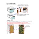
MFPC PWB replacement procedure
Technical Bulletin
|
4
|
903.41 KB
|
|
|
MX-C250 MX-C250E MX-C250F MX-C250FE MX-C250FR MX-C300F MX-C300W MX-C300WE MX-C300A MX-C300WR (serv.man39)
Starting Powder List (This list takes priority over information in Service Manuals).
Technical Bulletin
|
4
|
66.25 KB
|
|
|
MX-C250 MX-C250E MX-C250F MX-C250FE MX-C250FR MX-C300F MX-C300W MX-C300WE MX-C300A MX-C300WR (serv.man37)
Change in shape of open close lock pawl.
Technical Bulletin
|
3
|
97.28 KB
|
|
|
MX-C250 MX-C250E MX-C250F MX-C250FE MX-C250FR MX-C300F MX-C300W MX-C300WE MX-C300A MX-C300WR (serv.man36)
CCE-1501 CHANGE IN FERRITE CORE FOR FAX LINE CABLE
Technical Bulletin
|
2
|
79.44 KB
|
|
|
MX-C250 MX-C250E MX-C250F MX-C250FE MX-C250FR MX-C300F MX-C300W MX-C300WE MX-C300A MX-C300WR (serv.man34)
CHANGE ALONG WITH DISCONTINUATION OF MANUFACTURE OF AC INLET
Technical Bulletin
|
2
|
510.09 KB
|

|
MX-C250 MX-C250E MX-C250F MX-C250FE MX-C250FR MX-C300F MX-C300W MX-C300WE MX-C300A MX-C300WR (serv.man26)
Rom Upgrade 1 Firmware V1.07.E1.00
Driver / Update
|
|
26.02 MB
|

|
MX-C250 MX-C250E MX-C250F MX-C250FE MX-C250FR MX-C300F MX-C300W MX-C300WE MX-C300A MX-C300WR (serv.man25)
Rom Upgrade Version 2 01.07.E1.b0 (Fax Ring Issues)
Driver / Update
|
|
26.02 MB
|

|
MX-C250 MX-C250E MX-C250F MX-C250FE MX-C250FR MX-C300F MX-C300W MX-C300WE MX-C300A MX-C300WR (serv.man24)
Combined MFP Firmware Version ICU 01.08.E1 - Production Run OCT 2013 - Release Bulletin To Follow
Driver / Update
|
|
26.07 MB
|

|
MX-C250 MX-C250E MX-C250F MX-C250FE MX-C250FR MX-C300F MX-C300W MX-C300WE MX-C300A MX-C300WR (serv.man23)
Combined MFP Firmware Version ICU 01.10.E1
Driver / Update
|
|
26.06 MB
|

|
MX-C250 MX-C250E MX-C250F MX-C250FE MX-C250FR MX-C300F MX-C300W MX-C300WE MX-C300A MX-C300WR (serv.man22)
CCE1301 02.02.E1.00 ROM Update (Bulletin Embedded)
Driver / Update
|
|
26.11 MB
|

|
MX-C250 MX-C250E MX-C250F MX-C250FE MX-C250FR MX-C300F MX-C300W MX-C300WE MX-C300A MX-C300WR (serv.man21)
CCE-1317 OPEN SSL VULNERABILITY FIRMWARE RELEASE FOR FIELD SUPPORT VERSION V 0203E1b0 Bulletin embedded
Driver / Update
|
|
26.29 MB
|

|
MX-C250 MX-C250E MX-C250F MX-C250FE MX-C250FR MX-C300F MX-C300W MX-C300WE MX-C300A MX-C300WR (serv.man20)
Combined MFP Firmware Version ICU 02.05.E1
Driver / Update
|
|
26.37 MB
|

|
MX-C250 MX-C250E MX-C250F MX-C250FE MX-C250FR MX-C300F MX-C300W MX-C300WE MX-C300A MX-C300WR (serv.man19)
CCE-1459 Firmware update 02.06.E1
Driver / Update
|
|
35.21 MB
|
|
|
MX-C250 MX-C250E MX-C250F MX-C250FE MX-C250FR MX-C300F MX-C300W MX-C300WE MX-C300A MX-C300WR (serv.man18)
CCE1474 ENHANCEMENT OF MFPC PWB
Driver / Update
|
2
|
133.99 KB
|

|
MX-C250 MX-C250E MX-C250F MX-C250FE MX-C250FR MX-C300F MX-C300W MX-C300WE MX-C300A MX-C300WR (serv.man17)
Bulletin to follow.
Driver / Update
|
|
35.12 MB
|

|
MX-C250 MX-C250E MX-C250F MX-C250FE MX-C250FR MX-C300F MX-C300W MX-C300WE MX-C300A MX-C300WR (serv.man16)
Rom Upgrade 02.07.E1.00 (Refer to tech bulletin CCE-1562)
Driver / Update
|
|
35.12 MB
|
|
|
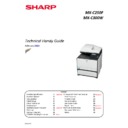
MX-C250 MX-C250E MX-C250F MX-C250FE MX-C250FR MX-C300F MX-C300W MX-C300WE MX-C300A MX-C300WR (serv.man2)
Handy Guide Feb 14
Handy Guide
|
34
|
2.7 MB
|
|
|
MX-C250 MX-C250E MX-C250F MX-C250FE MX-C250FR MX-C300F MX-C300W MX-C300WE MX-C300A MX-C300WR (serv.man3)
INFO REQUIRED FOR EE-PROM PROGRAMMING
Handy Guide
|
1
|
67.23 KB
|
|
|
MX-C250 MX-C250E MX-C250F MX-C250FE MX-C250FR MX-C300F MX-C300W MX-C300WE MX-C300A MX-C300WR
EEPROM Programming Procedure
Handy Guide
|
4
|
772.27 KB
|

|
MX-C250 MX-C250E MX-C250F MX-C250FE MX-C250FR MX-C300F MX-C300W MX-C300WE MX-C300A MX-C300WR (serv.man27)
Neo Training video (27 mins)
FAQ
|
|
143.64 MB
|
|
|
MX-C250 MX-C250E MX-C250F MX-C250FE MX-C250FR MX-C300F MX-C300W MX-C300WE MX-C300A MX-C300WR (serv.man79)
MSDS for MXC30GV-B Black Developer
Regulatory Data
|
5
|
43.31 KB
|
|
|
MX-C250 MX-C250E MX-C250F MX-C250FE MX-C250FR MX-C300F MX-C300W MX-C300WE MX-C300A MX-C300WR (serv.man80)
MSDS for MXC30GV-C Cyan Developer
Regulatory Data
|
4
|
40.17 KB
|
|
|
MX-C250 MX-C250E MX-C250F MX-C250FE MX-C250FR MX-C300F MX-C300W MX-C300WE MX-C300A MX-C300WR (serv.man81)
MSDS for MXC30GV-M Magenta Developer
Regulatory Data
|
4
|
40.29 KB
|
|
|
MX-C250 MX-C250E MX-C250F MX-C250FE MX-C250FR MX-C300F MX-C300W MX-C300WE MX-C300A MX-C300WR (serv.man82)
MSDS for MXC30GV-Y Yellow Developer
Regulatory Data
|
4
|
40.33 KB
|
|
|
MX-C250 MX-C250E MX-C250F MX-C250FE MX-C250FR MX-C300F MX-C300W MX-C300WE MX-C300A MX-C300WR (serv.man83)
MSDS for MXC30GT-B Black toner
Regulatory Data
|
5
|
42.76 KB
|
|
|
MX-C250 MX-C250E MX-C250F MX-C250FE MX-C250FR MX-C300F MX-C300W MX-C300WE MX-C300A MX-C300WR (serv.man84)
MSDS for MXC30GT-C Cyan toner
Regulatory Data
|
4
|
39.1 KB
|
|
|
MX-C250 MX-C250E MX-C250F MX-C250FE MX-C250FR MX-C300F MX-C300W MX-C300WE MX-C300A MX-C300WR (serv.man85)
MSDS for MXC30GT-M Magenta toner
Regulatory Data
|
4
|
39.12 KB
|
|
|
MX-C250 MX-C250E MX-C250F MX-C250FE MX-C250FR MX-C300F MX-C300W MX-C300WE MX-C300A MX-C300WR (serv.man86)
MSDS for MXC30GT-Y Yellow toner
Regulatory Data
|
4
|
39.22 KB
|

