Read Sharp MX-5500N / MX-6200N / MX-7000N (serv.man46) Service Manual online
MX-7000N SIMULATION 7 – 1
MX-7000N
Service Manual
[7] SIMULATION
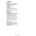
1. General
There are the following simulation functions for grasping the
machine operating conditions, troubleshooting, early detection of
trouble causes, speedy setting and adjustments, and improve-
ments in servicing.
1)
machine operating conditions, troubleshooting, early detection of
trouble causes, speedy setting and adjustments, and improve-
ments in servicing.
1)
Various adjustments
2)
Setting of the specifications and functions
3)
Canceling troubles
4)
Operation check
5)
Counters check, setting, clear
6)
Machine operating conditions (operation hysteresis), data
check, clear
check, clear
7)
Various (adjustments, setting, operation, counters, etc.) data
transfer
transfer
The operating procedures and displays depend on the form of the
operation panel of the machine.
operation panel of the machine.
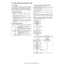
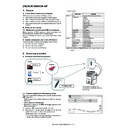
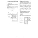
A. Basic operation
(1) Starting the simulation
* Entering the simulation mode
1)
1)
Copy mode key ON
→ Program key ON → Asterisk (*) key ON
→ CLEAR key ON → Asterisk (*) key ON (Ready for input of a
main code of simulation)
main code of simulation)
2)
Entering a main code with the 10-key
→ START key ON
3)
Entering a sub code with the 10-key
→ START key ON
4)
Select an item with the scroll key and the item key.
5)
The machine enters the mode corresponding to the selected
item.
Press START key or EXECUTE key to start the simulation
operation.
To cancel the current simulation mode or to change the main
code and the sub code, press the user setup key.
item.
Press START key or EXECUTE key to start the simulation
operation.
To cancel the current simulation mode or to change the main
code and the sub code, press the user setup key.
* Canceling the simulation mode to return to the normal mode
1)
1)
Press CA key.
(Note for the simulation mode)
• Do not turn OFF the power switch on the operation panel when
• Do not turn OFF the power switch on the operation panel when
the machine is in the simulation mode.
If the power switch should be turned OFF in the simulation mode,
a malfunction may be resulted. In this case, turn OFF/ON the
main power source.
If the power switch should be turned OFF in the simulation mode,
a malfunction may be resulted. In this case, turn OFF/ON the
main power source.
• Before entering the simulation mode, check to insure that neither
print data nor FAX data are receiving.
MX-7000N SIMULATION 7 – 2
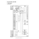
;'5
YES
NO
NO
YES
YES
YES
NO
NO
NO
YES
NO
YES
YES
NO
NO
YES
YES
NO
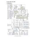
Standby for entry of SIM
sub code
Enter SIM sub code with
the 10-key.
Press the START button.
The display is made according
to the selected mode and the item.
START (Copy mode)
Press the Program key.
Press the asterisk (*) key.
Press the clear key.
Press the Program key.
Standby for entry of
SIM code.
Enter the main code of
SIM with the 10-key.
The main code of SIM
is displayed.
Press the START button.
Is there a sub code ?
Select the mode and the
item with the scroll key
and the item key.
Operation check ?
Operating conditions
check ?
Data clear ?
Adjustments
or setting (counter data
change) ?
Do you
want to change the
content ?
Enter the new setting and
adjustment values.
Press the SYSTEM
SETTINGS key
Press the SYSTEM
SETTINGS key
Press the EXECUTE button
and OK button.
Operation is made according
to the selected mode and item.
Press the EXECUTE button
and OK button.
Press the EXECUTE button
and OK button.
The display is made according to
the selected some and the item.
Press the EXECUTE button
and OK button.
Is it the same
simulation main
code?
Do you want
to perform another
simulation ?
Do you
want to end the
simulation ?
The changed content
is stored.
The simulation mode
is canceled.
Press the clear all key.
Operation is made according
to the selected mode and the item.
(Other modes)
The selected mode and
the item are cleared.
<Exclusion type>
You have to exit
simulation mode
before entering into
this mode for self
printing type.
In the power OFF/ON type
simulation, OFF/ON
message is
displayed by the
SYSTEM
SETTINGS key.
If there is no item.
MX-7000N SIMULATION 7 – 3
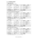
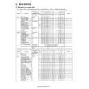
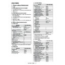
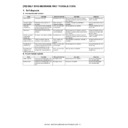
2. List of simulation codes
Main
Sub
Function (Purpose)
Purpose
Section
1
1
Used to check the operations of the scanner (read) unit and its control
circuit.
circuit.
Operation test/Check
Optical (Image scanning)
2
Used to check the operation of sensor in the scanning (read) section and the
related circuit.
related circuit.
Operation test/Check
Optical (Image scanning)
5
Used to check the operations of the scanner (read) unit and its control
circuit.
circuit.
Operation test/Check
Optical (Image scanning)
2
1
Used to check the operations of the automatic document feeder unit and the
control circuit.
control circuit.
Operation test/Check
DSPF
2
Used to check the operations of the sensors and detectors in the automatic
document feeder unit and the control circuits.
document feeder unit and the control circuits.
Operation test/Check
DSPF
3
Used to check the operations of the loads in the automatic document feeder
unit and the control circuits.
unit and the control circuits.
Operation test/Check
DSPF
3
2
Used to check the operation of sensor and detector in the finisher and the
control circuits.
control circuits.
Operation test/Check
Finisher
3
Used to check the operation of the load in the finisher and the control circuit.
Operation test/Check
Finisher
10
Used to adjust the finisher.
Adjustment
Finisher
30
Used to check the operations of the sensors and detectors in the inserter
and the control circuits.
and the control circuits.
Operation test/Check
Inserter
31
Used to check the operations of the loads in the inserter and the control
circuit.
circuit.
Operation test/Check
Inserter
32
Used to set the adjustment value of the inserter paper width detection level.
Setting (Adjustment)
Inserter
4
2
Used to check the operations of the sensors and detectors in the large
capacity tray (LCC) and the control circuit.
capacity tray (LCC) and the control circuit.
Operation test/Check
Large capacity tray (LCC)
3
Used to check the operations of the loads in the large capacity tray (LCC)
and the control circuit.
and the control circuit.
Operation test/Check
Large capacity tray (LCC)
5
Used to check the operations of the clutch (LTRC) in the LCC and the
monitor.
monitor.
Operation test/Check
Large capacity tray (LCC)
5
1
Used to check the operation of the display, LCD in the operation panel, and
control circuit.
control circuit.
Operation test/Check
Operation panel
2
Used to check the operation of the heater lamp and the control circuit.
Operation test/Check
Fusing
3
Used to check the operation of the copy lamp and the control circuit.
Operation test/Check
Optical (Image scanning)
4
Used to check the operation of the discharge lamp and the control circuit.
Operation test/Check
Process
6
1
Used to check the operations of the loads (clutches and solenoids) in the
paper transport system and the control circuits.
paper transport system and the control circuits.
Operation test/Check
Paper transport/paper exit
2
Used to check the operations of each fan motor and its control circuit.
Operation test/Check
Other
3
Used to check the operations of the primary transfer unit and the control
circuit.
circuit.
Operation test/Check
Process (Transfer)
4
Used to check the operations of the PTC and the MC cleaner.
Operation test/Check
7
1
Used to set the operating conditions of aging.
Setting
Other
6
Used to set the intermittent aging cycle.
Setting
8
Used to display the warm-up time.
Operation display
9
Used to set a color in the color mode printing. (Used to check the print in the
color mode.)
color mode.)
Operation test/Check
8
1
Used to check and adjust the operations of the developing voltage in each
print mode and the control circuit.
* When the middle speed is adjusted, the high speed and the low speed are
also adjusted simultaneously.
print mode and the control circuit.
* When the middle speed is adjusted, the high speed and the low speed are
also adjusted simultaneously.
Operation test/Check/Adjustment
Process (Developing)
2
Used to check and adjust the operations of the main charger grid voltage in
each printer mode and the control circuit.
* When the middle speed is adjusted, the high speed and the low speed are
also adjusted simultaneously.
each printer mode and the control circuit.
* When the middle speed is adjusted, the high speed and the low speed are
also adjusted simultaneously.
Operation test/Check/Adjustment
Process (Charging)
6
Used to check and adjust the operation of the transfer voltage and the
control circuit.
control circuit.
Operation test/Check/Adjustment
Process (Transfer)
9
2
Used to check the operations of the sensors and detectors in the duplex
section and its control circuit.
section and its control circuit.
Operation test/Check
Duplex
3
Used to check the operations of the loads in the duplex section and the
control circuits.
control circuits.
Operation test/Check
Duplex
10
1
Used to check the operation of the load (motor) in the process section and
the related circuits.
* This check must be performed with no toner bottle installed.
the related circuits.
* This check must be performed with no toner bottle installed.
Operation test/Check
Process (Developing)
2
Used to check the operations of the toner remaining quantity sensor and the
control circuit.
control circuit.
Operation test/Check
Process (Developing)
13
-
Used to cancel the self-diag "U1" trouble.
Clear/cancel (Trouble etc.)
14
-
Used to cancel excluding the self-diag "U1/U2/LCC/PF" troubles.
Clear/cancel (Trouble etc.)
15
-
Used to cancel the self-diag "U6-09, F3-12, F3-22 (large capacity paper feed
tray, paper feed tray 1, 2)" trouble.
tray, paper feed tray 1, 2)" trouble.
Clear/cancel (Trouble etc.)
LCC
16
-
Used to cancel the self-diag "U2" trouble.
Clear/cancel (Trouble etc.)
MFPcnt PWB /
PCU PWB / SCU PWB
PCU PWB / SCU PWB
17
-
Used to cancel the self-diag "PF" trouble.
Clear/cancel (Trouble etc.)
21
1
Used to set the maintenance cycle.
Setting
MX-7000N SIMULATION 7 – 4
22
1
Used to check the print count value in each section and operation mode.
(Used to check the maintenance timing.)
(Used to check the maintenance timing.)
Adjustment/Setting/Operation data
output/Check
output/Check
2
Used to check the total numbers of misfeed and troubles. (When the number
of total jam is considerably great, it is judged as necessary for repair.)
of total jam is considerably great, it is judged as necessary for repair.)
Adjustment/Setting/Operation data
check
check
3
Used to check the misfeed positions and the number of misfeed at each
position.
* The trouble position can be troubleshooted according to this data.
position.
* The trouble position can be troubleshooted according to this data.
Adjustment/Setting/Operation data
check
check
4
Used to check the trouble (self diag) history.
Adjustment/Setting/Operation data
check
check
5
Used to check the ROM version of each unit (section).
Other
6
Used to output the list of the setting and adjustment data (simulations, FAX
soft switch, counters).
soft switch, counters).
Adjustment/Setting/Operation data
check
check
8
Used to check the counter value of the finisher, the DSPF, and the scan
(reading).
(reading).
Adjustment/Setting/Operation data
check
check
9
Used to check the number of use (print quantity) of each paper feed section.
Adjustment/Setting/Operation data
check
check
Paper feed, ADU, LCC
10
Used to check the system configuration (option, internal hardware).
Adjustment/Setting/Operation data
check
check
11
Used to check the use frequency of FAX (send/receive). (Only when FAX is
installed.)
installed.)
Adjustment/Setting/Operation data
check
check
FAX
12
Used to check the misfeed position in the DSPF and the number of misfeed
of each position. (If the number of misfeed is considerably great, it may lead
to the decision for repair.)
of each position. (If the number of misfeed is considerably great, it may lead
to the decision for repair.)
Adjustment/Setting/Operation data
check
check
DSPF
13
Used to check the running time of the process section. (OPC drum, DV unit,
toner bottle).
toner bottle).
Adjustment/Setting/Operation data
check
check
19
Used to check each counter value related the network scanner.
Adjustment/Setting/Operation data
check
check
90
Used to output the list of various set data.
Adjustment/Setting/Operation data
check
check
23
2
Used to check the trouble history of paper jam and misfeed. (If the number of
misfeed and troubles is considerably great, it may be judged as necessary to
repair.)
misfeed and troubles is considerably great, it may be judged as necessary to
repair.)
Adjustment/Setting/Operation data
check
check
80
Used to check the operations of the sensors and detectors in the paper feed
and transport section.
and transport section.
Operation test/Check
Paper feed, transport
24
1
Used to clear the jam counter, and the trouble counter. (The counters are
cleared after completion of maintenance.)
cleared after completion of maintenance.)
Data clear
2
Used to clear the number of use (the number of prints) of each paper feed
section.
section.
Data clear
3
Used to clear the counter value of the finisher, the DSPF, and scan
(reading).
(reading).
Data clear
4
The maintenance counter and the print counters of the transfer unit and the
fusing unit are cleared. (After completion of maintenance, the counters are
cleared.)
fusing unit are cleared. (After completion of maintenance, the counters are
cleared.)
Data clear
5
Used to clear the developer counter. (After replacement of developer, this
counter is cleared.)
counter is cleared.)
Data clear
6
Used to clear the copy counter value.
Data clear
7
Used to clear the OPC drum counter value. (After replacement of the OPC
drum, this counter is cleared.)
drum, this counter is cleared.)
Data clear
9
Used to clear the printer mode print counter and the self print mode print
counter.
counter.
Data clear
10
Used to clear the FAX counter value. (Only when FAX is installed.)
Data clear
15
Used to clear various counters in the scan mode related to image send.
Data clear
30
Used to initialize the administrator password.
Data clear
31
Used to initialize the service mode password.
Data clear
25
1
Used to check the operations of the developing section.
Operation test/Check
Process (Developing
section)
section)
2
Used to make the initial setting of the toner density when replacing
developer. (Automatic adjustment)
developer. (Automatic adjustment)
Setting
Process (Photoconductor/
Developing/Transfer/
Cleaning)
Developing/Transfer/
Cleaning)
26
2
Used to set the paper size of the large capacity tray (LCC). (When the paper
size is changed, this simulation must be executed to change the paper size
in software.)
size is changed, this simulation must be executed to change the paper size
in software.)
Setting
Paper feed
3
Used to set the auditor setting mode. (Setting must be made according to
the auditor use conditions.)
the auditor use conditions.)
Setting
Auditor
5
Used to set the count mode of the total counter and the maintenance
counter.
counter.
Setting
6
Used to set the specifications according to the destination. (Paper, fixed
magnification ratios, etc.)
magnification ratios, etc.)
Setting
10
Used to set the trial mode of the network scanner.
Setting
18
Used to set Disable/Enable of the toner save mode operation. (For the
Japan and the UK versions.)
Japan and the UK versions.)
Setting
30
Used to set the operation mode corresponding to the CE mark (Europe
safety standards). (For slow start to drive the fusing heater lamp)
safety standards). (For slow start to drive the fusing heater lamp)
Setting
Main
Sub
Function (Purpose)
Purpose
Section

