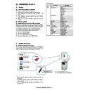
Read Sharp MX-4100N / MX-4101N / MX-5000N / MX-5001N (serv.man32) Service Manual online
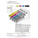
MX-4101N FUSER SECTION M – 1
MX-4101N
Service Manual
[M] FUSER SECTION
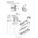
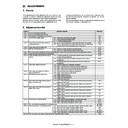
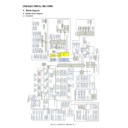
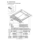
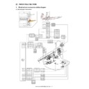
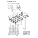
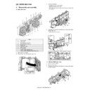
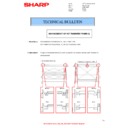
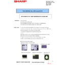
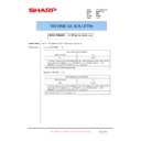
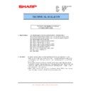
1. Electrical and mechanism relation diagram
P
ᴜᴶᴳᴉų
RWZ
R
CN2
B03P-VL-K
CN4
HL
PWB
PCU
P
WB
B03P-VL-RD
CN3
B08B-PASK
B2P3-VH
CN14
R
S
M-3pin(BK)
P
BK
WH
BL
P
D
F1B-20DE
E
CN13
R
S
M-2pin
P
B32B-PHDSS
R
S
M-2pin
P
R
S
M-4pin
P
P
S
M-2pin
R
B34B-PHDSS
RCZR
10PIN
TH_LM_IN
TH_EX2_IN
16
D-GND
/HL_PR
D-GND
D-GND
D-GND
2
HL_OUT_EX
INT24V1
N,C
N,C
N,C
1
N-HL(US)
1
HL_OUT_UM
8
12
INT24V1
D-GND
HL_OUT_US
4
6
N-HL(UM)
1
L-HL
U
3
3
N
-HL(EX)
2
N,C
TH_UMCS_IN
2
2
B-9
22
6
3
2
1
5
1
6
16
16
D-GND
18
D-GND
14
TH_UM_IN
18
HL_OUT_EX
HL_OUT_LM
6
N-HL(EX)
3
L-HL(LM)
2
N-HL(LM)
1
N-HL(US)
5
N-HL(UM)
L-HL
U
4
5
15
D-GND
2
19
19
15
11
14
13
13
D-GND
WEBD
11
D-GND
1
TH_UMCS_IN
10
WEBD
12
TH_EX1_IN
17
D-GND
TH_LM_IN
9
TH_EX2_IN
7
5
10
88
66
44
D-GND
A-9
A-1
A-10
5VN
A-1
A-2
11
13
17
D-GND
A-8
D-GND
4
1
D-GND
2
TH_EX1_IN
3
TH_EX2_IN
B-3
D-GND
1
TH_LM_IN
1
2
B-4
B-7
B-6
TH_UM_IN
1
1
3
2
1
2
TH_UMCS_IN
D-GND
7
5
6
3
1
L-HL(LM)
2
B-2
B-1
TH_UM_IN
TH_UM_IN
HL_OUT_UM
8
D-GND
B-8
B-7
12
14
14
TH_US_IN
D-GND
TH_EX1_IN
1
RCZR
9PIN
B-9
TH_LM_IN
A-7
D-GND
A-8
A-10
WEBD
A-9
3
77
9
9
A-5
A-4
A-6
A-3
5
1
1
2
5VN
D-GND
A-7
A-6
A-5
A-2
A-3
A-4
3
B-5
B-8
B-6
B-4
B-3
B-2
B-5
TH_EX2_IN
D-GND
D-GND
B-1
TH_UMCS_IN
4
3
N-HL(LM)
10
8
D-GND
HL_OUT_US
2
1
5VN
10
TH_EX1_IN
3
2
/HL_PR
HL_OUT_LM
12
TH_US_IN
4
TH_US_IN
3
2
4
2
D-GND
TH_US_IN
4
1
W
EBD
2D
-G
N
D
3
1
CN14 INT24V1 P-GND /FUM_CK
2
5
/FUM_D
29
FUM_LD
31
27
CN13
DF1B-26Pin
INT24V1
D-GND
32
31
19
19
WEB_M2out
18
WEB_M1out
18
P
SL-2Pin
R
2
WEB_M2out
2
1
WEB_M1out
1
R
SM-12Pin
P
/FUM_D
1
INT24V1
4
1
6
6
NC
4
5
5
FUM_LD
5
2
2
P-GND
3
3
/FUM_CK
WEBM
WEB-END
FUM
TH_UM
TH_LM
TH_US
TS SUB
TS MAIN
TS EX1
TH_EX1
TH_EX2
TS EX2
HL_EX2
HL_EX1
HL_UM
HL_LM
1
5
2
2
3
4
6
6
2
MX-4101N FUSER SECTION M – 2
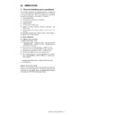
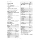
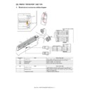
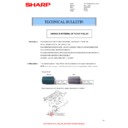
2. Operational descriptions
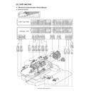
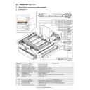
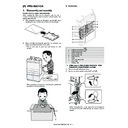
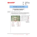
A. Fusing unit drive
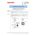
For driving the fusing unit, the drive power is transmitted from the
drive motor (FUM) through the connection gear to the upper heat
roller gear.
Driving by the drive motor (stepping motor) is performed according
to the control signal sent from the PCU.
drive motor (FUM) through the connection gear to the upper heat
roller gear.
Driving by the drive motor (stepping motor) is performed according
to the control signal sent from the PCU.
B. Heater lamp drive
The surface temperature of the heat roller detected by the ther-
mistor is sent to the PCU. When the temperature is lower than the
specified level, the heater lamp ON signal is sent from the PCU to
the heater lamp drive circuit on the HL PWB.
The power triac in the heater lamp drive circuit is turned on, and the
AC power is supplied to the heater lamp, lighting the lamp and
heating the heat roller.
To prepare for an abnormally high temperature of the heat roller,
the thermostat is provided for safety.
When the thermostat is opened, the power supply (AC line) to the
heater lamp is cut off.
C. Fusing operation
Color toner (Y,M,C,K) on paper is subject to heat and pressure to
be fused on paper.
At that time, color toner of Y, M, C, and K are mixed to reproduce
colors approximate to the document image colors.
The heater lamps are provided in the lower and the upper heat
roller to heat paper from the upper and the lower sides.
This is because paper must be heated both from the upper side
and from the lower side together in order to melt and fuse toner in
the four layers on the paper.
The upper and the lower heat rollers of silicon rubber are
employed.
This is because of the following reasons.
1)
To increase the nip quantity. To increase the heating capacity
for paper.
for paper.
2)
By pressing the flexible roller, multi-layer toner can be fused
without deformation.
without deformation.
3)
An even pressure can be applied to rough surface of toner lay-
ers (multi-layer structure).
ers (multi-layer structure).
Signal name
Name
Function/Operation
FUM
Fusing motor
Drives the fusing unit.
HL_LM
Heater lamp lower main
Heats the fusing roller (pressing).
HL_UM
Heater lamp upper main
Heats the fusing roller (heating).
HL_EX1
Heater lamp external 1
Heats the fusing roller (heating). (External)
HL_EX2
Heater lamp external 2
Heats the fusing roller (heating). (External)
HLPCD
Fusing pressure release sensor Detects pressure release of the fusing roller.
TS MAIN
Thermostat (1)
Shuts conduction to the heater lamp when the temperature rises abnormally. [For the fusing roller (heating)]
TS EX1
Thermostat (2)
Shuts conduction to the heater lamp when the temperature rises abnormally. [For the fusing roller (heating)]
(External)
(External)
TS EX2
Thermostat (3)
When the temperature rises abnormally, conduction to the heater lamp is cut off.
[For the fusing roller (heating)] (External)
[For the fusing roller (heating)] (External)
TS SUB
Thermostat (4)
When the temperature rises abnormally, conduction to the heater lamp is cut off.
[For the fusing roller (pressing)] (External)
[For the fusing roller (pressing)] (External)
PRM
Fusing pressure release motor
Adjusts the fusing roller pressure.
TH_UM
Fusing temperature sensor (1)
Detects the surface temperature of the fusing roller (heating). (Center section)
TH_US
Fusing temperature sensor (2)
Detects the surface temperature of the fusing roller (heating). (Edge section)
TH_LM
Fusing temperature sensor (3)
Detects the surface temperature of the fusing roller (pressing).
TH_EX1
Fusing temperature sensor (4)
Detects the surface temperature of the heat roller (external).
TH_EX2
Fusing temperature sensor (5)
Detects the surface temperature of the heat roller (external).
No.
Name
Function/Operation
1
Fusing roller (Heating)
Applies heat and pressure to toner on paper to fuse it on paper.
2
Upper separation pawl
Mechanically separates paper which was not naturally separated from the fusing roller (heating).
3
Fusing roller (Pressing)
Applies heat and pressure to toner on paper to fuse it on paper.
4
Transport roller 9 (Drive)
Transports paper from the fusing roller to the paper exit roller 1.
5
Web roller
Cleans the upper heat roller.
6
Lower separation pawl
Mechanically separates paper which was not naturally separated from the fusing roller (pressing).
FUM
PCU
MX-4101N FUSER SECTION M – 3
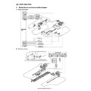
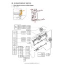
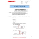
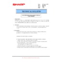
D. Automatic pressure release system
The upper and the lower heat rollers are normally pressed. When,
however, one of the following conditions is satisfied, they are
released from the pressure.
• When the machine shifts to the pre-heating mode.
• When the machine shifts to the auto power shut off mode.
• When the power switch of the operation panel is turned OFF.
• When the machine has been left in the ready state for 20 min-
utes.
• When the envelope mode is used.
(1) Pressure release operation
The pressure release motor (PRM) rotates to drive the pressure
release lever of the fusing unit to the pressure release state via the
reduction gears (6 pcs.).
When 1710ms passes from operating the pressure release detec-
tion level and driving the pressure release sensor (HLPCD) to the
transmission state (L level), the pressure release motor stops to
complete the pressure release operation.
(2) Pressing operation
When an end use performs any operation or when the machine
receives a job signal, the pressure release motor rotates reversely
to dive the pressure release lever to the pressing state.
When 430ms passes from when the pressure release sensor
(HLPCD) is in the interruption state (H level), the pressure motor
stops to complete the pressing operation.
receives a job signal, the pressure release motor rotates reversely
to dive the pressure release lever to the pressing state.
When 430ms passes from when the pressure release sensor
(HLPCD) is in the interruption state (H level), the pressure motor
stops to complete the pressing operation.
NOTE: When turning OFF the main power switch of the machine,
be sure to turn OFF the power switch of the operation
panel and check to confirm that the LCD is turned OFF.
If the main power switch is turned OFF with the LCD dis-
played, the power is tu5ned off without completion of the
pressure release operation. This will deform the upper and
the lower heat rollers.
When, in addition, the fusing roller is installed again after
removing it, be sure to install it under the pressure release
state.
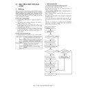
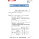
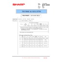
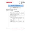
E. Fusing temperature control
The temperature sensor is provided at the center and the edge sec-
tion of the upper heat roller and at the edge section of the lower
heat roller.
The heat roller temperature is detected by each temperature sen-
sor to control the heater lamp to maintain the temperature at the
specified level.
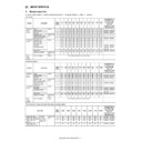
In addition, the fusing temperature is switched according to the kind
of paper.
In the case of SW-A
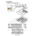
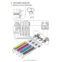
3. Disassembly and assembly
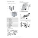
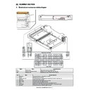
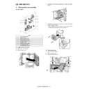
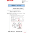
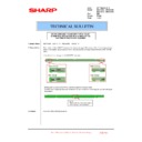
A. Fusing unit
1)
Open the right door.
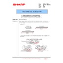
Pressure release lever
Pressure release
motor (PRM)
motor (PRM)
Pressing condition
Pressure release
state
state
Mode
Paper
Upper
heater
lamp main
Upper
heater
external
Lower
heater
heater
lamp main
Ready
condition
Print mode
condition
Print mode
Black/White
plain paper
plain paper
170
220
125
Color plain
paper
paper
170
220
130
Thick paper
185
220
140
OHP
180
220
140
Envelope
200
220
140
Glossy paper
185
220
140
Parts
a
Upper thermostat
b
Lower thermostat
c
External thermostat
d
Upper heater lamp
e
Lower heater lamp
f
External heater lamp
g
Fusing cleaning roller / Fusing cleaning roller bearing
a
b
d
e
g
c
c
f
f
MX-4101N FUSER SECTION M – 4
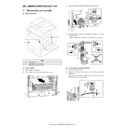
2)
Remove the blue screw and the step screw. Release the lock
lever and remove the fusing unit.
lever and remove the fusing unit.
(1) Upper thermostat
1)
Remove the fusing unit.
2)
Remove the screw. Pull out the interface harness and remove
the fusing upper cover.
the fusing upper cover.
3)
Remove the screw, and remove the terminal. Remove the
upper thermostat.
* Install so that the caulked section of the terminal faces up.
upper thermostat.
* Install so that the caulked section of the terminal faces up.
(2) Lower thermostat
1)
Remove the fusing unit.
2)
Remove the screw, and remove the fusing lower cover.
3)
Remove the screw, and remove the terminal. Remove the
lower thermostat.
* Install so that the caulked section of the terminal faces
lower thermostat.
* Install so that the caulked section of the terminal faces
down.
(3) External thermostat
1)
Remove the fusing unit.
2)
Remove the fusing upper cover.
3)
Remove the screw, and remove the terminal. Remove the
external thermostat.
* Install so that the caulked section of the terminal faces up.
external thermostat.
* Install so that the caulked section of the terminal faces up.
2
1
1
1
3
2

