Read Sharp AR-TR2 (serv.man2) Service Manual online
CODE: 00ZARTR2//A1E
DIGITAL COPIER
OPTION
JOB SEPARATOR
OPTION
JOB SEPARATOR
MODEL
AR-TR2
Parts marked with “ ” is important for maintaining the safety of the set. Be sure to replace these parts with specified ones
for maintaining the safety and performance of the set.
for maintaining the safety and performance of the set.
[ 1 ] PRODUCT OUTLINE . . . . . . . . . . . . . . . . . . . . . . . . . . . . . . . . . . 1-1
[ 2 ] SYSTEM DIAGRAM . . . . . . . . . . . . . . . . . . . . . . . . . . . . . . . . . . . 1-1
[ 3 ] SPECIFICATIONS . . . . . . . . . . . . . . . . . . . . . . . . . . . . . . . . . . . . 1-1
[ 4 ] UNPACKING AND INSTALLATION . . . . . . . . . . . . . . . . . . . . . . . 1-1
[ 5 ] OPERATIONAL DESCRIPTION . . . . . . . . . . . . . . . . . . . . . . . . . 1-4
[ 6 ] SIMULATIONS . . . . . . . . . . . . . . . . . . . . . . . . . . . . . . . . . . . . . . . 6-1
[ 7 ] TROUBLE CODES . . . . . . . . . . . . . . . . . . . . . . . . . . . . . . . . . . . 6-1
PARTS GUIDE
CONTENTS
AR-TR2
SHARP CORPORATION
[1] PRODUCT OUTLINE
This machine is a job separator of printing and copying for the FAX and the printer of the digital copier.
[2] SYSTEM DIAGRAM
Option or standard
Job separator
Intermediate paper exit tray
Separator motor unit
Digital copier
Printer kit
FAX kit
< AR-TR2 >
[3] SPECIFICATIONS
Top step
Job
Printer/FAX
Capacity
About 100 sheets
Bottom step
Job
Copy
Capacity
About 150 sheets
Full detection
Available (Job separator top step only)
Offset function
By the shifter (Digital copier function)
Stapling capacity
None
[4] UNPACKING AND INSTALLATION
1. Items packed togather
2. Installing proccedure
1) Turn off the main switch which is on the side of the copier, and
disconnect the power plug from the power outlet.
2) Open the manual paper feed tray and the right door, and remove
the right door.
•
Open the manual paper feed tray of the copier body, and
remove the right door.
remove the right door.
3) Open the front cover, and remove the developer unit.
•
Open the front cover. Push up the lock release lever of the
developing unit to release the lock. Pull out the developing unit
slowly, and hold the knob to remove the developing unit.
developing unit to release the lock. Pull out the developing unit
slowly, and hold the knob to remove the developing unit.
Separator tray
FULL detection mylar
ATC spacer
Separator motor unit
Screw (P tight M3) 1 pc
Installation Manual
Lock release lever
Front cover
Knob
AR-TR2
1 – 1
4) Remove the front cover.
•
Pull out the paper cassette. Push the both sides of the front
cover to bend it inward, and remove it from the hinge arm of
the copier.
cover to bend it inward, and remove it from the hinge arm of
the copier.
5) Remove the front cover and the right cover of the copier.
•
Open the document cover. Remove the fixing screws (5 pcs.)
of the right cover, and remove the right cover.
Then remove the fixing screws (12 pcs.) of the front cover, and
remove the front cover. At that time, pull out the flat cable from
the operation panel at first. Since the grounding wire is con-
nected to the front cabinet, put the front cabinet on the left side
of the copier.
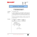
6) Cut off the paper exit auxiliary mylar, and attach the FULL detec-
tion mylar. (This procedure is performed only in Japan.)
•
Cut off the two paper exit mylars inside the copier with scis-
sors. Then clean and remove oil from the attaching surface of
the FULL detection lever, and attach the FULL detection mylar
as shown in the figure.
sors. Then clean and remove oil from the attaching surface of
the FULL detection lever, and attach the FULL detection mylar
as shown in the figure.
7) Shift the separator lever.
•
Turn the separator gear to move the lever upward until it stops.
8) Install the separator tray.
•
Put the separator tray inside the copier, and engage the R/F
bosses of the separator tray with the R/F sides of the separator
lever of the copier, and install the separator tray to the copier.
bosses of the separator tray with the R/F sides of the separator
lever of the copier, and install the separator tray to the copier.
9) Cut off the optical molt. (If there is no optical molt, this procedure
is not required.)
•
If the optical molt is considerably long, cut off the shaded sec-
tion of the separator motor installing section in the right frame
of the copier with a cutter.
tion of the separator motor installing section in the right frame
of the copier with a cutter.
Attachment
reference
reference
Cut position
AR-TR2
1 – 2
10)Install the separator motor unit.
•
Insert the separator motor unit into the positioning place and fix
it with the screw. At that time, check that the grounding plate is
at the position shown in the figure of the frame below.
it with the screw. At that time, check that the grounding plate is
at the position shown in the figure of the frame below.
11)Connect the connector and store it.
•
Connect the separator motor connector with the copier side
connector, and store them as shown.
connector, and store them as shown.
12)Install the ATC spacer.
•
Press the pawl on the right side of the fan to remove the fan.
Attach the ATC spacer to the shaft, and fix it to the position
shown below so that the clearance comes in front. Return and
fix the fan to the original position.
Attach the ATC spacer to the shaft, and fix it to the position
shown below so that the clearance comes in front. Return and
fix the fan to the original position.
13)Install the front cabinet and the right cabinet of the copier.
•
Install the right cabinet to the original position, and fix it with the
five screws. Connect the flat cable to the operation panel, and
install the front cabinet to the original position. and fix it with the
12 screws. Close the original cover.
five screws. Connect the flat cable to the operation panel, and
install the front cabinet to the original position. and fix it with the
12 screws. Close the original cover.
14)Install the front cover.
•
Press the both sides of the front cover inward to bend the
cover, and install it to the hinge arm. Close the paper cassette.
cover, and install it to the hinge arm. Close the paper cassette.
15)Install the developing unit.
•
Hold the developing unit knob, and insert it slowly until it stops.
16)Install the right door of the copier and close the front cover and
the tray.
•
Install the right door, then close the tray and the front cover.
Pawl
Knob
AR-TR2
1 – 3

