|
|
AR-PB2 (serv.man4)
ARPB2 Service Manual
Service Manual
|
59
|
1.67 MB
|
|
|
AR-PB2A (serv.man7)
ARPB2A-Service Manual
Service Manual
|
32
|
607.47 KB
|
|
|
AR-PB2 (serv.man6)
ARPB2 Supplement Operation Guide (This includes all installation information needed for the v3 printer drivers, NWSetup, Status Monitor and Sharp Admin software)
User Guide / Operation Manual
|
20
|
79.8 KB
|
|
|
AR-PB2 (serv.man7)
Revised ARPB2 Operation Manual
User Guide / Operation Manual
|
60
|
311.75 KB
|
|
|
AR-PB2A (serv.man9)
ARPB2a Operation Manual
User Guide / Operation Manual
|
78
|
491.88 KB
|

|
AR-PB2A
Modified PPD's for Mac OS X (v10.2.2). Mac OS
Drivers
|
|
60.8 KB
|

|
AR-PB2A (serv.man2)
Apple Mac OS 8 9 PPD. Mac OS
Drivers
|
|
568.28 KB
|

|
AR-PB2A (serv.man3)
Apple Mac OS X Driver Installer. Mac OS
Drivers
|
|
50.53 KB
|

|
AR-PB2A (serv.man43)
Combined PCL5e PCL6 PS Driver (Build 1.3L.006) for Win2k for Cougar 2000 models only, supporting Win2k 2003 Server with WHQL. Windows 2000
Drivers
|
|
5.82 MB
|

|
AR-PB2A (serv.man44)
Windows 2000 PS driver version 8.0.0 build 004 (Cougar 2000 models only). Windows 2000
Drivers
|
|
1.86 MB
|

|
AR-PB2A (serv.man45)
Windows 2000 Pcl6 driver version 6.0.0 build 005 (Cougar 2000 models only). Windows 2000
Drivers
|
|
1.86 MB
|

|
AR-PB2A (serv.man46)
Windows 2000 Pcl5e driver version 6.0.0 build 005 (Cougar 2000 models only). Windows 2000
Drivers
|
|
1.89 MB
|

|
AR-PB2A (serv.man47)
Windows 2000 WHQL certified Pcl5e driver version 5.0.0 build 002 (Cougar 2000 models only). Windows 2000
Drivers
|
|
1.76 MB
|

|
AR-PB2A (serv.man48)
Windows 2000 WHQL certified Pcl6 driver version 5.0.0 build 002 (Cougar 2000 models only). Windows 2000
Drivers
|
|
1.75 MB
|

|
AR-PB2A (serv.man49)
Windows 2000 WHQL certified Postscript driver version 7.0.0 build 002 (Cougar 2000 models only). Windows 2000
Drivers
|
|
1.74 MB
|

|
AR-PB2A (serv.man50)
Windows 2000 WHQL certified Postscript PPD (Cougar 2000 models only). Windows 2000
Drivers
|
|
30.5 KB
|

|
AR-PB2A (serv.man51)
Combined PCL5e PCL6 PS Driver (Build 1.3L.006)for WinXP for Cougar 2000 models only, supporting Win2k 2003 Server with WHQL. Windows XP
Drivers
|
|
5.82 MB
|

|
AR-PB2A (serv.man52)
Windows XP PS driver version 8.0.0 build 004 (Cougar 2000 models only). Windows XP
Drivers
|
|
1.86 MB
|

|
AR-PB2A (serv.man53)
Windows XP Pcl6 driver version 6.0.0 build 005 (Cougar 2000 models only). Windows XP
Drivers
|
|
1.86 MB
|

|
AR-PB2A (serv.man54)
Windows XP Pcl5e driver version 6.0.0 build 005 (Cougar 2000 models only). Windows XP
Drivers
|
|
1.89 MB
|

|
AR-PB2A (serv.man55)
Windows XP WHQL certified Pcl5e driver version 5.0.0 build 002 (Cougar 2000 models only). Windows XP
Drivers
|
|
1.76 MB
|

|
AR-PB2A (serv.man56)
Windows XP WHQL certified Pcl6 driver version 5.0.0 build 002 (Cougar 2000 machines only). Windows XP
Drivers
|
|
1.75 MB
|

|
AR-PB2A (serv.man57)
Windows XP WHQL certified Postscript driver version 7.0.0 build 002 (Cougar 2000 machines only). Windows XP
Drivers
|
|
1.74 MB
|

|
AR-PB2A (serv.man58)
Windows XP WHQL certified Postscript PPD (Cougar 2000 machines only). Windows XP
Drivers
|
|
30.5 KB
|

|
AR-PB2A (serv.man59)
Combined PCL5e PCL6 PS Driver (Build 1.3L.005) for WinNT4.0 for Cougar 2000 models only, supporting Win2k 2003 Server. Windows NT4
Drivers
|
|
5.8 MB
|

|
AR-PB2A (serv.man60)
Windows NT4 PS version 8.0.0 build 004. Windows NT4
Drivers
|
|
1.86 MB
|

|
AR-PB2A (serv.man61)
Windows NT4 Pcl6 version 6.0.0 build 005. Windows NT4
Drivers
|
|
1.85 MB
|

|
AR-PB2A (serv.man62)
Windows NT4 Pcl5e, version 6.0.0 build 005. Windows NT4
Drivers
|
|
1.87 MB
|

|
AR-PB2A (serv.man63)
Windows NT4 Pcl5e, version 5.0.0 build 001. Windows NT4
Drivers
|
|
3.41 MB
|

|
AR-PB2A (serv.man64)
Windows NT4 Pcl6, version 5.0.0 build 001. Windows NT4
Drivers
|
|
3.38 MB
|

|
AR-PB2A (serv.man65)
Windows NT4 Postscript driver, version 7.0.0 build 001. Windows NT4
Drivers
|
|
3.41 MB
|

|
AR-PB2A (serv.man66)
Windows NT4 Postscript PPD. Windows NT4
Drivers
|
|
96.08 KB
|

|
AR-PB2A (serv.man67)
Windows ME PS driver version 8.0.0 build 004. Windows ME
Drivers
|
|
2.72 MB
|

|
AR-PB2A (serv.man68)
Windows ME Pcl6 driver version 6.0.0 build 005. Windows ME
Drivers
|
|
2.8 MB
|

|
AR-PB2A (serv.man69)
Windows ME Pcl5e driver version 6.0.0 build 005. Windows ME
Drivers
|
|
2.81 MB
|

|
AR-PB2A (serv.man70)
Windows ME WHQL certified Pcl5e driver version 5.0.0 build 001. Windows ME
Drivers
|
|
5.04 MB
|

|
AR-PB2A (serv.man71)
Windows ME WHQL certified Pcl6 driver version 5.0.0 build 001. Windows ME
Drivers
|
|
5.02 MB
|

|
AR-PB2A (serv.man72)
Windows ME WHQL certified Postscript driver version 6.0.0 build 001. Windows ME
Drivers
|
|
4.37 MB
|

|
AR-PB2A (serv.man73)
Windows ME WHQL certified Postscript PPD. Windows ME
Drivers
|
|
147.48 KB
|

|
AR-PB2A (serv.man74)
Windows 9x PS driver version 8.0.0 build 004. Windows 98
Drivers
|
|
2.72 MB
|

|
AR-PB2A (serv.man75)
Windows 9x Pcl6 driver version 6.0.0 build 005. Windows 98
Drivers
|
|
2.8 MB
|

|
AR-PB2A (serv.man76)
Windows 9x Pcl5e driver version 6.0.0 build 005. Windows 98
Drivers
|
|
2.81 MB
|

|
AR-PB2A (serv.man77)
Windows 9x Pcl5e driver version 5.0.0 build 001. Windows 98
Drivers
|
|
5.04 MB
|

|
AR-PB2A (serv.man78)
Windows 9x Pcl6 driver version 5.0.0 build 001. Windows 98
Drivers
|
|
5.02 MB
|

|
AR-PB2A (serv.man79)
Windows 9x Postscript driver version 6.0.0 build 001. Windows 98
Drivers
|
|
4.37 MB
|

|
AR-PB2A (serv.man80)
Windows 9x Postscript PPD. Windows 98
Drivers
|
|
147.48 KB
|
|
|
AR-PB2A (serv.man8)
ARPB2A-Parts Guide
Parts Guide
|
10
|
328.6 KB
|
|
|
AR-PB2 (serv.man3)
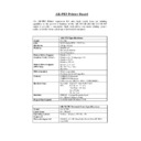
AR-PB2 Printer Board Specifications
Specification
|
4
|
16.24 KB
|
|
|
AR-PB2A (serv.man6)
ARPB2A-Specifications
Specification
|
9
|
77.45 KB
|
|
|
AR-PB2 (serv.man29)
ARPB2a-011a Release of ARPB2a v4.405 Program Font Firmware
Technical Bulletin
|
1
|
45.68 KB
|
|
|
AR-PB2 (serv.man30)
ARPB2-013 Release of ARPB2a version 5 drivers
Technical Bulletin
|
2
|
13.21 KB
|
|
|
AR-PB2 (serv.man31)
ARPB2-012 ARPB2 Printer Board Version History
Technical Bulletin
|
9
|
174.8 KB
|
|
|
AR-PB2 (serv.man32)
ARPB2-011 Release of ARPB2a v4.40 Program Font Firmware
Technical Bulletin
|
1
|
9.9 KB
|
|
|
AR-PB2 (serv.man33)
ARPB2-010 How to fully remove AR-PB2 Printer Drivers from Windows 95 98 NT4 2000 systems Updated version supporting v5 drivers
Technical Bulletin
|
11
|
81.65 KB
|
|
|
AR-PB2 (serv.man34)
ARPB2-009 Release of the ARPB2a Drivers Firmware
Technical Bulletin
|
2
|
51.81 KB
|
|
|
AR-PB2 (serv.man35)
ARPB2-008 Fixing F9 00 error messages
Technical Bulletin
|
2
|
15.03 KB
|
|
|
AR-PB2 (serv.man36)
ARPB2-007 How to fully remove Sharp ARPB2 Printer Drivers
Technical Bulletin
|
6
|
62.03 KB
|
|
|
AR-PB2 (serv.man37)
ARPB2-006 Information on the new ARPB2 Drivers Firmware
Technical Bulletin
|
1
|
9.88 KB
|
|
|
AR-PB2 (serv.man38)
ARPB2-005 Modified Relay Connector for ARPB2 Printer Board when fitting ARNC3D Network Card
Technical Bulletin
|
1
|
9.74 KB
|
|
|
AR-PB2 (serv.man39)
ARPB2-004 Setting up a Windows NT4.0 Print Queue for Apple Macintosh clients
Technical Bulletin
|
2
|
11.65 KB
|
|
|
AR-PB2 (serv.man40)
ARPB2-003 Printing from an Apple Macintosh Computer
Technical Bulletin
|
2
|
10.45 KB
|
|
|
AR-PB2 (serv.man41)
ARPB2-002 Printing Microsoft Excel Worksheets from within an Excel Workbook
Technical Bulletin
|
2
|
8.28 KB
|
|
|
AR-PB2 (serv.man42)
ARPB2-001 Installation of print drivers under Windows 95 98
Technical Bulletin
|
4
|
531.77 KB
|
|
|
AR-PB2A (serv.man25)
Modified ARPB2-012 ARPB2 Printer Driver Version History
Technical Bulletin
|
15
|
183.92 KB
|
|
|
AR-PB2A (serv.man26)
ARPB2-017 Installing the SAP Device Type for Sharp Printers
Technical Bulletin
|
14
|
433.02 KB
|
|
|
AR-PB2A (serv.man27)
ARPB2-016 Distribution of a configured printer driver from Windows 2000 and NT4.0
Technical Bulletin
|
7
|
771.57 KB
|
|
|
AR-PB2A (serv.man28)
ARPB2-015 Distribution of a configured printer driver from NetWare 5.x
Technical Bulletin
|
11
|
1.67 MB
|
|
|
AR-PB2A (serv.man29)
ARPB2-014 Extracting a Sharp Printer s configuration from the Windows Registry
Technical Bulletin
|
3
|
127.84 KB
|

|
AR-PB2A (serv.man30)
Digital Signature
Technical Bulletin
|
|
33.07 KB
|
|
|
AR-PB2A (serv.man31)
ARPB2-013 Release of ARPB2a version 5 drivers
Technical Bulletin
|
2
|
13.21 KB
|
|
|
AR-PB2A (serv.man32)
Release of ARPB2a v4.405 Program Font Firmware
Technical Bulletin
|
1
|
45.68 KB
|
|
|
AR-PB2A (serv.man33)
ARPB2-010 How to fully remove AR-PB2 Printer Drivers from Windows 95 98 NT4 2000 systems Updated version supporting v5 drivers
Technical Bulletin
|
11
|
81.65 KB
|
|
|
AR-PB2A (serv.man34)
ARPB2-009 Release of the ARPB2a Drivers Firmware
Technical Bulletin
|
2
|
51.81 KB
|
|
|
AR-PB2A (serv.man35)
ARPB2-008 Fixing F9 00 error messages
Technical Bulletin
|
2
|
51.77 KB
|
|
|
AR-PB2A (serv.man36)
ARPB2-007 How to fully remove Sharp ARPB2 Printer Drivers
Technical Bulletin
|
6
|
62.03 KB
|
|
|
AR-PB2A (serv.man37)
ARPB2-006 Information on the new ARPB2 Drivers Firmware
Technical Bulletin
|
1
|
9.88 KB
|
|
|
AR-PB2A (serv.man38)
ARPB2-005 Modified Relay Connector for ARPB2 Printer Board when fitting ARNC3D Network Card
Technical Bulletin
|
1
|
9.74 KB
|
|
|
AR-PB2A (serv.man39)
ARPB2-004 Setting up a Windows NT4.0 Print Queue for Apple Macintosh clients
Technical Bulletin
|
2
|
11.65 KB
|
|
|
AR-PB2A (serv.man40)
ARPB2-003 Printing from an Apple Macintosh Computer
Technical Bulletin
|
2
|
10.45 KB
|
|
|
AR-PB2A (serv.man41)
ARPB2-002 Printing Microsoft Excel Worksheets from within an Excel Workbook
Technical Bulletin
|
2
|
8.28 KB
|
|
|
AR-PB2A (serv.man42)
ARPB2-001 Installation of print drivers under Windows 95 98
Technical Bulletin
|
4
|
531.77 KB
|

|
AR-PB2 (serv.man9)
New Driver Removal batch Files v2.2 that support Windows 95 98 NT4 2000. Updated version supporting v5 drivers
Driver / Update
|
|
86.24 KB
|
|
|
AR-PB2 (serv.man10)
Please Read Me before installing the ARPB2 V3 Printer Drivers
Driver / Update
|
1
|
2.14 KB
|

|
AR-PB2 (serv.man11)
OLD PB2 firmware PRT-2.32 Boot-1.11
Driver / Update
|
|
5.26 MB
|

|
AR-PB2 (serv.man12)
Taken from ARPB2a CD)
Driver / Update
|
|
1.5 MB
|

|
AR-PB2 (serv.man13)
It will turn the ARPB2 in to an ARPB2 )
Driver / Update
|
|
152.34 KB
|

|
AR-PB2 (serv.man14)
It will turn the ARPB2 in to an ARPB2 ).
Driver / Update
|
|
4.19 MB
|

|
AR-PB2 (serv.man15)
AR-PB2 Apple Macintosh PPD Print Driver files (this file is compressed into Stuffit format so that it may be transported o a PC floppy disk).
Driver / Update
|
|
47.94 KB
|

|
AR-PB2 (serv.man16)
Apple Macintosh PPD Printer Driver for ARPB2 . (This file is a self extracting archive which must be downloaded directly to a Mac but will not require stuffit to uncompress it).
Driver / Update
|
|
47.91 KB
|

|
AR-PB2 (serv.man17)
ARPB2 V3 Windows 3.xx PCL5E Printer Driver
Driver / Update
|
|
2.38 MB
|

|
AR-PB2 (serv.man18)
ARPB2 V3 Windows 3.xx Postscript Level 2 Printer Driver
Driver / Update
|
|
2.07 MB
|

|
AR-PB2 (serv.man19)
ARPB2 V3 Windows 95 98 PCL5E Printer Driver
Driver / Update
|
|
2.38 MB
|

|
AR-PB2 (serv.man20)
ARPB2 V3 Windows 95 98 PCL6 Printer Driver
Driver / Update
|
|
2.34 MB
|

|
AR-PB2 (serv.man21)
ARPB2 V3 Windows 95 98 Postscript Level 2 Printer Driver
Driver / Update
|
|
2.07 MB
|

|
AR-PB2 (serv.man22)
ARPB2 V3 Windows 95 98 Postscript PPD Printer Driver
Driver / Update
|
|
105.04 KB
|

|
AR-PB2 (serv.man23)
ARPB2 V3 Windows NT4 PCL5E Printer Driver
Driver / Update
|
|
1.53 MB
|

|
AR-PB2 (serv.man24)
ARPB2 V3 Windows NT4 PCL6 Printer Driver
Driver / Update
|
|
1.47 MB
|

|
AR-PB2 (serv.man25)
ARPB2 V3 Windows NT4 Postscript Level 2 Printer Driver
Driver / Update
|
|
1.49 MB
|

|
AR-PB2 (serv.man26)
ARPB2 V3 Windows NT4 Postscript PPD Printer Driver
Driver / Update
|
|
66.24 KB
|

|
AR-PB2 (serv.man27)
See Supplement Operation Manual for details)
Driver / Update
|
|
493.88 KB
|

|
AR-PB2 (serv.man28)
NWsetup Software (This software can be used to configure an ARNC1D ARNC3D on a Novell 4 server)
Driver / Update
|
|
743.89 KB
|

|
AR-PB2A (serv.man12)
Firmware Rev 4.437 (includes various bug fixes).
Driver / Update
|
|
4.72 MB
|

|
AR-PB2A (serv.man13)
Fixes PS error when printing 256dpi image (or images not providing dpi info)
Driver / Update
|
|
4.7 MB
|

|
AR-PB2A (serv.man14)
NT Uninstaller. This utility will allow you to remove the driver for a specific model from a Windows NT PC and runs without the need to reboot between deleting the printer and removing the driver files.
Driver / Update
|
|
11.83 KB
|

|
AR-PB2A (serv.man15)
Zsharp Printer Device Type file to support ARPB2 on SAP systems
Driver / Update
|
|
72.55 KB
|

|
AR-PB2A (serv.man16)
TrueType Fonts for Cougar Resident fonts
Driver / Update
|
|
2.27 MB
|

|
AR-PB2A (serv.man17)
Win3.1 PS latest driver
Driver / Update
|
|
3.88 MB
|

|
AR-PB2A (serv.man18)
Win3.1 PCL5e latest driver
Driver / Update
|
|
4.76 MB
|

|
AR-PB2A (serv.man19)
New Driver Removal batch Files v2.2 that support Windows 95 98 NT4 2000. Updated version supporting v5 drivers
Driver / Update
|
|
86.24 KB
|

|
AR-PB2A (serv.man20)
SPUD (Sharp Printing Utility for DOS. Allows a dos print file to be printed duplex, from a specific tray, to a specific output tray etc.
Driver / Update
|
|
20.79 KB
|

|
AR-PB2A (serv.man21)
Sharp Status Monitor v2.1 (Taken from the ARPB2a v1.2 CD)
Driver / Update
|
|
1.56 MB
|

|
AR-PB2A (serv.man22)
Sharp Printer Administration Utility v2.5 (Taken from the ARPB2a v1.2 CD)
Driver / Update
|
|
1.72 MB
|

|
AR-PB2A (serv.man23)
Apple Mac PPD's (4th Generation of drivers).
Driver / Update
|
|
568.28 KB
|

|
AR-PB2A (serv.man24)
Boot ROM firmware version 2.04 for use with AR-PB2a. When upgrading from PB2 , this firmware must be upgraded first. NOTE It is very important that the procedure in the enclosed RTF file is followed.
Driver / Update
|
|
159.89 KB
|
|
|
AR-PB2
Cougar Connectivity Training Pre-course study guide (Glossary of Terms)
Handy Guide
|
18
|
295.06 KB
|
|
|
AR-PB2 (serv.man2)
Boot program Font Flash Memory Upgrade Procedure
Handy Guide
|
5
|
108.33 KB
|
|
|
AR-PB2A (serv.man4)
Cougar Connectivity Training Pre-course study guide (Glossary of Terms)
Handy Guide
|
18
|
295.06 KB
|
|
|
AR-PB2A (serv.man5)
ARPB2 ARPB2a Boot Font Flash Memory Upgrade Procedure
Handy Guide
|
5
|
108.33 KB
|
|
|
AR-PB2 (serv.man8)
Including ARPB2a queries)
FAQ
|
15
|
295.16 KB
|
|
|
AR-PB2A (serv.man10)
Commands for selection of paper input and output trays. Including Escape codes, PJL commands and Postscript commands.
FAQ
|
2
|
77.31 KB
|
|
|
AR-PB2A (serv.man11)
Including ARPB2a queries)
FAQ
|
15
|
295.16 KB
|

