|
|
AR-P350 AR-P450 (serv.man6)
AR350 450 Series Basic Service Manual
Service Manual
|
54
|
6 MB
|
|
|
AR-P350 AR-P450 (serv.man7)
ARP350 and ARP450-Circuit Diagrams
Service Manual
|
90
|
6.67 MB
|
|
|
AR-P350 AR-P450 (serv.man22)
ARP M350 450-Operation Manual (Printer)
User Guide / Operation Manual
|
8
|
178.32 KB
|

|
AR-P350 AR-P450
ARM350 450 Drivers for Mac OS 10.1 to 10.6. Requires ARPK1 PS Option. Mac OS
Drivers
|
|
16.9 MB
|

|
AR-P350 AR-P450 (serv.man2)
Modified PPD's for Mac OS X (v10.2.2). Mac OS
Drivers
|
|
64.52 KB
|

|
AR-P350 AR-P450 (serv.man3)
Apple Mac OS X Driver Installer. Mac OS
Drivers
|
|
747.31 KB
|

|
AR-P350 AR-P450 (serv.man4)
Apple Mac OS 8 9 Driver Installer. Mac OS
Drivers
|
|
1.6 MB
|

|
AR-P350 AR-P450 (serv.man85)
Windows NT PCL6 driver version 4.0.0 build 071. Windows 2000
Drivers
|
|
1.1 MB
|

|
AR-P350 AR-P450 (serv.man86)
Windows 2000 PCL5e driver version 4.0.0 build 071. Windows 2000
Drivers
|
|
1.14 MB
|

|
AR-P350 AR-P450 (serv.man87)
Windows 2000 PCL6 driver version 4.0.0 build 071. Windows 2000
Drivers
|
|
1.11 MB
|

|
AR-P350 AR-P450 (serv.man88)
Windows 2000 PCL6 driver version 2.2.0u build 067, which supports different first page in pamphlet mode. Windows 2000
Drivers
|
|
1.05 MB
|

|
AR-P350 AR-P450 (serv.man89)
Windows 2000 PCL5e driver version 2.2.0u build 067, which supports different first page in pamphlet mode. Windows 2000
Drivers
|
|
1.08 MB
|

|
AR-P350 AR-P450 (serv.man90)
Windows 2000 WHQL Certified Postscript PPD. Windows 2000
Drivers
|
|
35.2 KB
|

|
AR-P350 AR-P450 (serv.man91)
Windows 2000 WHQL Certified Postscript driver version 2.2.0 build 066. Windows 2000
Drivers
|
|
2.26 MB
|

|
AR-P350 AR-P450 (serv.man92)
Windows 2000 WHQL Certified PCL6 driver version 2.2.0 build 065. Windows 2000
Drivers
|
|
1.06 MB
|

|
AR-P350 AR-P450 (serv.man93)
Windows 2000 WHQL Certified PCL5e driver version 2.2.0 build 065. Windows 2000
Drivers
|
|
1.08 MB
|

|
AR-P350 AR-P450 (serv.man94)
Windows XP PCL5e driver version 4.0.0 build 071. Windows XP
Drivers
|
|
1.14 MB
|

|
AR-P350 AR-P450 (serv.man95)
Windows XP PCL6 driver version 4.0.0 build 071. Windows XP
Drivers
|
|
1.11 MB
|

|
AR-P350 AR-P450 (serv.man96)
Windows XP PCL6 driver version 2.2.0u build 067, which supports different first page in pamphlet mode. Windows XP
Drivers
|
|
1.05 MB
|

|
AR-P350 AR-P450 (serv.man97)
Windows XP PCL5e driver version 2.2.0u build 067, which supports different first page in pamphlet mode. Windows XP
Drivers
|
|
1.08 MB
|

|
AR-P350 AR-P450 (serv.man98)
Windows XP WHQL Certified POSTSCRIPT driver version 2.2.0 build 066. Windows XP
Drivers
|
|
2.26 MB
|

|
AR-P350 AR-P450 (serv.man99)
Windows XP WHQL Certified PCL6 driver version 2.2.0 build 065. Windows XP
Drivers
|
|
1.06 MB
|

|
AR-P350 AR-P450 (serv.man100)
Windows XP WHQL Certified PCL5e driver version 2.2.0 build 065. Windows XP
Drivers
|
|
1.08 MB
|

|
AR-P350 AR-P450 (serv.man101)
Windows NT PCL6 driver version 4.0.0 build 071. Windows NT4
Drivers
|
|
1.1 MB
|

|
AR-P350 AR-P450 (serv.man102)
Windows NT PCL5e driver version 4.0.0 build 071. Windows NT4
Drivers
|
|
1.13 MB
|

|
AR-P350 AR-P450 (serv.man103)
Windows NT PCL6 driver version 2.2.0u build 067, which supports different first page in pamphlet mode. Windows NT4
Drivers
|
|
1.05 MB
|

|
AR-P350 AR-P450 (serv.man104)
Windows NT PCL5e driver version 2.2.0u build 067, which supports different first page in pamphlet mode. Windows NT4
Drivers
|
|
1.08 MB
|

|
AR-P350 AR-P450 (serv.man105)
Windows NT4 Postscript PPD. Windows NT4
Drivers
|
|
179.57 KB
|

|
AR-P350 AR-P450 (serv.man106)
Windows NT4 Postscript driver version 2.2.0 build 066. Windows NT4
Drivers
|
|
2.26 MB
|

|
AR-P350 AR-P450 (serv.man107)
Windows NT4 PCL6 driver version 2.2.0 build 065. Windows NT4
Drivers
|
|
1.05 MB
|

|
AR-P350 AR-P450 (serv.man108)
Windows NT4 PCL5 driver version 2.2.0 build 065. Windows NT4
Drivers
|
|
1.07 MB
|

|
AR-P350 AR-P450 (serv.man109)
Windows ME PCL5e driver version 4.0.0 build 071. Windows ME
Drivers
|
|
1.29 MB
|

|
AR-P350 AR-P450 (serv.man110)
Windows ME PCL6 driver version 4.0.0 build 071. Windows ME
Drivers
|
|
1.29 MB
|

|
AR-P350 AR-P450 (serv.man111)
Windows ME PCL6 driver version 2.2.0u build 067, which supports different first page in pamphlet mode. Windows ME
Drivers
|
|
1.3 MB
|

|
AR-P350 AR-P450 (serv.man112)
Windows ME PCL5e driver version 2.2.0u build 067, which supports different first page in pamphlet mode. Windows ME
Drivers
|
|
1.3 MB
|

|
AR-P350 AR-P450 (serv.man113)
Windows ME WHQL Certified Postscript PPD. Windows ME
Drivers
|
|
299.95 KB
|

|
AR-P350 AR-P450 (serv.man114)
Windows ME WHQL Certified Postscript driver version 2.2.0 build 065. Windows ME
Drivers
|
|
2.63 MB
|

|
AR-P350 AR-P450 (serv.man115)
Windows ME WHQL Certified PCL6 driver version 2.2.0 build 065. Windows ME
Drivers
|
|
1.3 MB
|

|
AR-P350 AR-P450 (serv.man116)
Windows ME WHQL Certified PCL5e driver version 2.2.0 build 065. Windows ME
Drivers
|
|
1.3 MB
|

|
AR-P350 AR-P450 (serv.man117)
Windows ME PCL5e driver version 4.0.0 build 071. Windows 98
Drivers
|
|
1.29 MB
|

|
AR-P350 AR-P450 (serv.man118)
Windows ME PCL6 driver version 4.0.0 build 071. Windows 98
Drivers
|
|
1.29 MB
|

|
AR-P350 AR-P450 (serv.man119)
Windows 98 PCL6 driver version 2.2.0u build 067, which supports different first page in pamphlet mode. Windows 98
Drivers
|
|
1.3 MB
|

|
AR-P350 AR-P450 (serv.man120)
Windows 98 PCL5e driver version 2.2.0u build 067, which supports different first page in pamphlet mode. Windows 98
Drivers
|
|
1.3 MB
|

|
AR-P350 AR-P450 (serv.man121)
Windows 95 98 Postscript PPD. Windows 98
Drivers
|
|
299.95 KB
|

|
AR-P350 AR-P450 (serv.man122)
Windows 95 98 Postscript driver version 2.2.0 build 065. Windows 98
Drivers
|
|
2.63 MB
|

|
AR-P350 AR-P450 (serv.man123)
Windows 95 98 PCL6 driver version 2.2.0 build 065. Windows 98
Drivers
|
|
1.3 MB
|

|
AR-P350 AR-P450 (serv.man124)
Windows 95 98 PCL5e driver version 2.2.0 build 065. Windows 98
Drivers
|
|
1.3 MB
|
|
|
AR-P350 AR-P450 (serv.man9)
Rear frame section 2, 17 - Packing material accessories.
Parts Guide
|
8
|
458.76 KB
|
|
|
AR-P350 AR-P450 (serv.man10)
Information of parts change to sections 7-Fusing Unit, 8-Delivery Turn Over Unit, 12-Controller Box Unit.
Parts Guide
|
8
|
639.72 KB
|
|
|
AR-P350 AR-P450 (serv.man11)
Informationof parts changes to sections 1 Exteriors, 5 TC unit, 6 Cassette paper feeder, 7 Fusing unit, 8 Delivery turn over unit, 14 Rear frame section 1, 15 Rear frame section 2, 16 Cassette unit, 17 Packing material accessories.
Parts Guide
|
20
|
1.33 MB
|
|
|
AR-P350 AR-P450 (serv.man12)
Packing material accessories
Parts Guide
|
6
|
134.79 KB
|
|
|
AR-P350 AR-P450 (serv.man13)
Cassette paper feeder, 8 - Delivery turn over unit.
Parts Guide
|
5
|
379.48 KB
|
|
|
AR-P350 AR-P450 (serv.man14)
Main drive unit, 7 - Fusing unit, 8 - Delivery turn over unit
Parts Guide
|
7
|
598.87 KB
|
|
|
AR-P350 AR-P450 (serv.man15)
Process unit, 12 - Controller box unit
Parts Guide
|
5
|
383.93 KB
|
|
|
AR-P350 AR-P450 (serv.man16)
Fusing Unit, 8 - Delivery Turnover Unit.
Parts Guide
|
5
|
395.8 KB
|
|
|
AR-P350 AR-P450 (serv.man17)
Left Door Unit, 7 - Fusing Unit, 12 - Controller Box Unit, 14 - Rear Frame Section 1, 15 - Rear Frame Section 2, 16 - Cassette Unit.
Parts Guide
|
13
|
1.05 MB
|
|
|
AR-P350 AR-P450 (serv.man18)
Fusing Unit, 8 - Delivery Turn Over Unit
Parts Guide
|
5
|
395.8 KB
|
|
|
AR-P350 AR-P450 (serv.man19)
11 Developer unit.
Parts Guide
|
3
|
140.92 KB
|
|
|
AR-P350 AR-P450 (serv.man20)
Parts Guide (Revised)
Parts Guide
|
39
|
2.63 MB
|
|
|
AR-P350 AR-P450 (serv.man21)
ARP350 and ARP450-Parts Guide
Parts Guide
|
51
|
2.65 MB
|
|
|
AR-P350 AR-P450 (serv.man40)
ARE-902 SMUDGY IMAGE RECEPTION RESULTING FROM INCOMPLETE MG ROLLER ROTATION
Technical Bulletin
|
2
|
69.87 KB
|
|
|
AR-P350 AR-P450 (serv.man41)
ROM upgrade 18
Technical Bulletin
|
2
|
10.33 KB
|
|
|
AR-P350 AR-P450 (serv.man42)
Reduction in E7-11 problem.
Technical Bulletin
|
2
|
31.74 KB
|
|
|
AR-P350 AR-P450 (serv.man43)
L6-10 POLYGON MOTOR LOCK
Technical Bulletin
|
1
|
180.7 KB
|
|
|
AR-P350 AR-P450 (serv.man44)
The improvement for paper jam at delivery turn over unit
Technical Bulletin
|
2
|
88.62 KB
|
|
|
AR-P350 AR-P450 (serv.man45)
Preventing fixing unit from dropping
Technical Bulletin
|
2
|
157.09 KB
|
|
|
AR-P350 AR-P450 (serv.man46)
Improvement in lead edge skew caused by warp of the transfer front PG
Technical Bulletin
|
1
|
97.99 KB
|
|
|
AR-P350 AR-P450 (serv.man47)
Improved strength PS coupling
Technical Bulletin
|
1
|
64.82 KB
|
|
|
AR-P350 AR-P450 (serv.man48)
Duct support plate changed and duct support cover added
Technical Bulletin
|
1
|
31.2 KB
|
|
|
AR-P350 AR-P450 (serv.man49)
Parts change to separator pawl solenoid and side plate
Technical Bulletin
|
1
|
12.85 KB
|
|
|
AR-P350 AR-P450 (serv.man50)
The leading edge shape of the Separation Pawl has changed
Technical Bulletin
|
2
|
117 KB
|
|
|
AR-P350 AR-P450 (serv.man51)
Flash ROM version upgrade procedure (Revised)
Technical Bulletin
|
3
|
71.65 KB
|
|
|
AR-P350 AR-P450 (serv.man52)
ROM upgrade
Technical Bulletin
|
6
|
563.55 KB
|
|
|
AR-P350 AR-P450 (serv.man53)
Supply of additional material
Technical Bulletin
|
3
|
145.73 KB
|
|
|
AR-P350 AR-P450 (serv.man54)
Updated ROM version
Technical Bulletin
|
7
|
279.85 KB
|
|
|
AR-P350 AR-P450 (serv.man55)
Parts change information
Technical Bulletin
|
2
|
59.47 KB
|
|
|
AR-P350 AR-P450 (serv.man56)
Parts change information
Technical Bulletin
|
2
|
35.61 KB
|
|
|
AR-P350 AR-P450 (serv.man57)
ARFN6 F1-87 ERROR
Technical Bulletin
|
2
|
504.95 KB
|
|
|
AR-P350 AR-P450 (serv.man58)
Paper jam in duplex mode from LCC tray of ARD13
Technical Bulletin
|
1
|
559.12 KB
|
|
|
AR-P350 AR-P450 (serv.man59)
Parts change information
Technical Bulletin
|
1
|
30.31 KB
|
|
|
AR-P350 AR-P450 (serv.man60)
Revision of the Service Manual (How to read the serial number of a developer cartridge)
Technical Bulletin
|
1
|
43.74 KB
|
|
|
AR-P350 AR-P450 (serv.man61)
Paper jam - MPFDNTD - from ARD13 14
Technical Bulletin
|
1
|
66.06 KB
|
|
|
AR-P350 AR-P450 (serv.man62)
Improving toner dispensing from toner cartridges
Technical Bulletin
|
1
|
39.84 KB
|
|
|
AR-P350 AR-P450 (serv.man63)
Parts change information
Technical Bulletin
|
2
|
58.71 KB
|
|
|
AR-P350 AR-P450 (serv.man64)
Information on combinations of software (ROM) versions
Technical Bulletin
|
2
|
136.96 KB
|
|
|
AR-P350 AR-P450 (serv.man65)
ARFN7 - broken staple unit
Technical Bulletin
|
3
|
1.67 MB
|
|
|
AR-P350 AR-P450 (serv.man66)
Parts changes
Technical Bulletin
|
2
|
502.7 KB
|
|
|
AR-P350 AR-P450 (serv.man67)
Parts change information
Technical Bulletin
|
1
|
60.47 KB
|
|
|
AR-P350 AR-P450 (serv.man68)
ROM upgrade for main unit
Technical Bulletin
|
2
|
28.96 KB
|
|
|
AR-P350 AR-P450 (serv.man69)
Part change information
Technical Bulletin
|
2
|
62.06 KB
|
|
|
AR-P350 AR-P450 (serv.man70)
Part change information
Technical Bulletin
|
3
|
131.94 KB
|
|
|
AR-P350 AR-P450 (serv.man71)
Action to strengthen the spring of the waste toner shutter section, and prevent it from becoming disengaged
Technical Bulletin
|
1
|
33.04 KB
|
|
|
AR-P350 AR-P450 (serv.man72)
Correction to the Service Manual
Technical Bulletin
|
1
|
21.24 KB
|
|
|
AR-P350 AR-P450 (serv.man73)
Change in adjustment procedure of the LSU squareness in accordance with the discontinuance of the LSU unit adjustment screw
Technical Bulletin
|
2
|
154.02 KB
|
|
|
AR-P350 AR-P450 (serv.man74)
Corrections to the parts guide
Technical Bulletin
|
2
|
112.83 KB
|
|
|
AR-P350 AR-P450 (serv.man75)
Change carried out in the heater PWB in the 200V heater kit
Technical Bulletin
|
1
|
29.8 KB
|
|
|
AR-P350 AR-P450 (serv.man76)
Change of pre-packed CD-ROM version to 13 languages
Technical Bulletin
|
1
|
30.15 KB
|
|
|
AR-P350 AR-P450 (serv.man77)
New offer of Auditor fixing kit
Technical Bulletin
|
1
|
22.29 KB
|
|
|
AR-P350 AR-P450 (serv.man78)
Parts change
Technical Bulletin
|
1
|
37 KB
|
|
|
AR-P350 AR-P450 (serv.man79)
ARDC1 Circuit diagram
Technical Bulletin
|
3
|
233.82 KB
|
|
|
AR-P350 AR-P450 (serv.man80)
Additional trouble codes
Technical Bulletin
|
2
|
36.5 KB
|

|
AR-P350 AR-P450 (serv.man29)
ARP350 450 Engine Firmware, This version will upgrade Main and PCU. (EjD11)
Driver / Update
|
|
5.03 MB
|

|
AR-P350 AR-P450 (serv.man30)
Printer Engine Firmware Main eJa11
Driver / Update
|
|
5.03 MB
|

|
AR-P350 AR-P450 (serv.man31)
ARP350 450 Engine Firmware, This version will upgrade Main and PCU. (Main Vej.10, PCU V9.04)
Driver / Update
|
|
5.03 MB
|

|
AR-P350 AR-P450 (serv.man32)
When printing from Unix, a overprinting of characters or staircase printing effect can be removed by downloading a PCL termination command to the Tiger. This zip contains the file and instructions.
Driver / Update
|
|
3.54 KB
|

|
AR-P350 AR-P450 (serv.man33)
ARP350 450 Engine Firmware (This version will upgrade Main PCU) (Main Ji.03 PCU 9.03.00)
Driver / Update
|
|
5.05 MB
|

|
AR-P350 AR-P450 (serv.man34)
ARP350 450 Engine Firmware (This version will upgrade Main PCU)(Main J.04 PCU 9.03.00)
Driver / Update
|
|
5.04 MB
|

|
AR-P350 AR-P450 (serv.man35)
Sharp Status Monitor v 3.1
Driver / Update
|
|
4.24 MB
|

|
AR-P350 AR-P450 (serv.man36)
Sharp Printer Administration Utility v3.1
Driver / Update
|
|
5.47 MB
|
|
|
AR-P350 AR-P450 (serv.man37)
Manual describing latest firmware updates
Driver / Update
|
4
|
50.65 KB
|

|
AR-P350 AR-P450 (serv.man38)
See Flash ROM Upgrade Procedure)
Driver / Update
|
|
7.94 KB
|
|
|
AR-P350 AR-P450 (serv.man39)
Flash ROM Upgrade Procedure
Driver / Update
|
2
|
58.51 KB
|
|
|
AR-P350 AR-P450 (serv.man5)
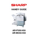
ARM350 450 ARP350 450 Handy Guide (NEW)
Handy Guide
|
40
|
642.38 KB
|

|
AR-P350 AR-P450 (serv.man23)
A complete list of PCL HPGL PJL PS commands, sometimes called Escape Commands for Tiger
FAQ
|
|
75.52 KB
|
|
|
AR-P350 AR-P450 (serv.man24)
ARP350 450 Engine Firmware Revision Table
FAQ
|
1
|
48.3 KB
|
|
|
AR-P350 AR-P450 (serv.man25)
Procedure to convert machines using AR450DM (50K Drum) to AR451DM (100K Drum). (Corrected)
FAQ
|
6
|
100.29 KB
|
|
|
AR-P350 AR-P450 (serv.man26)
Web Page Error code information. If you receive an error code whilst updating through the web page, this document should help explain what it means.
FAQ
|
6
|
226.72 KB
|
|
|
AR-P350 AR-P450 (serv.man27)
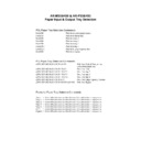
Commands for selection of paper input and output trays. Including Escape codes, PJL commands and Postscript commands.
FAQ
|
2
|
75.85 KB
|
|
|
AR-P350 AR-P450 (serv.man28)
ARM P350 450-Technical Launch Pack
FAQ
|
58
|
2.37 MB
|
|
|
AR-P350 AR-P450 (serv.man81)
Developer MSDS
Regulatory Data
|
2
|
10.82 KB
|
|
|
AR-P350 AR-P450 (serv.man82)
Toner MSDS
Regulatory Data
|
2
|
11.52 KB
|
|
|
AR-P350 AR-P450 (serv.man83)
Environmental Data Sheet (AR-P450)
Regulatory Data
|
1
|
6.1 KB
|
|
|
AR-P350 AR-P450 (serv.man84)
Environmental Data Sheet (AR-P350)
Regulatory Data
|
1
|
6.1 KB
|

