Read Sharp AR-M351U / AR-M451U (serv.man12) Service Manual online
AR-M351U/M451U, AR-M355U/M455U MAINTENANCE AND DETAILS OF EACH SECTION 7 - 21
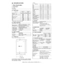
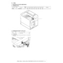
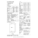
2. Fusing section
A. General
This section fused toner (which is transferred onto paper in the
transfer section) onto paper by heat and pressure of the fusing
roller.
transfer section) onto paper by heat and pressure of the fusing
roller.
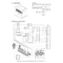
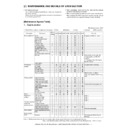
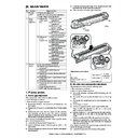
B. Major parts and signal functions
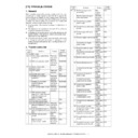
Copy
Paper
exit
exit
Fusing roller
(Heating)
(Heating)
Power/
Filter PWB
Filter PWB
Main
motor
motor
Paper exit
roller
roller
Heater lamps
(2 pcs.)
(2 pcs.)
Fusing roller
(Pressing)
(Pressing)
Cleaning
roller
roller
Fusing
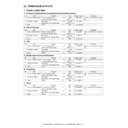
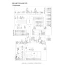
Rth1
MM
AC/DC
PWB
2
1
B-1
BR
HL2
2
3
RTH2
B-5
GY
2
BR
Rth2
HLTS
B-4
B-3
L2
1
2
GY
3
B-3
2
HL1
GND2
GND2
B-1
GY
4
4
HL2
3
BR
4
B-2
4
1
RTH1
3
BR
B-4
B03P-VL
CN1
3
1
GY
1
SMP-04V-NC+SMR-04V-N
1
HL2
GY
2
3
3
VLP-03V+VLR-03V
WH
HL1
2
1
L2
WH
BK
7
MSW MON
6
2
HLCNT1
CN2
5
3
(NC)
1
4
HLPR
HLCNT2
+24VPR
B7B-PH-K-S
DCCNT/
+24V1
12
+24V3
GND2
+3.3V1
6
GY
GY
CN5
7
BR
RD
RD
OR
GY
FW
3
GND2
+5V2
+24V2
GND2
1
11
GND2
+3.3V1
OR
GY
B12P-HL-A
2
9
+5V1
4
10
8
5
BR
BR
GY
BR
GY
BR
OR
GY
RD
RD
GY
GY
BR
BR
BR
RD
BR
OR
PCU
PWB
PWB
15
GND2
(NC)
CN14
2
14
+5V2
13
(NC)
6
11
10
8
RTH1
4
HLPR
6
4
+3.3V1
RTH2
1
3
GND
HLCNT1
GND
HLCNT2
MSW MON
9
GND2
12
+5V2
5
+24V1
+3.3V1
FW
5
7
16
CN17
+24VPR
GND2
8
GND2
3
+24V2
9
7
1
+12V2
BUP_PR
B16B-PH-K-S
GND2
2
B9P-VH
B-2
B-5
09R-RWZV-K2GGP4+CZHR-05V-S
REACTOR
PWB
PWB
200V ONLY
TAIWAN ONLY
WH
HL-L
3
2
1
HL-1N
HL-2N
WH
BR
WH
BK
BK
HL1
L2R
L
#187(BK)
#187(BK)
(NC)
2
1
L2
CN2
B03P-VL
B03P-VL
(NC)
L2R
3
4
CN1
B2P4-VH
B2P4-VH
BK
BK
SRA-51T-4
SRA-51T-4
2
L2
1
HL2
3
B03P-VL
CN1
HL1
1
HL2
GY
2
3
3
VLP-03V+VLR-03V
WH
HL1
2
1
L2
WH
BK
DSW-F
MM-T
GND2
+5V2
GND2
MM\
9604S-08C
1
2
3
4
5
6
7
8
CN9
DSW-F
GND2
DSW-L
MM-T
GND1
+5V2
GND2
MM\
DSW-L
GND1
8FE-ST-VK-N
8
7
6
5
4
3
2
1
7
8
9
1
9
3
4
6
5
7,8
2
10
FILTER PWB
L2in
1
2
3
L2out
(NC)
BK
BK
CN1
B03P-VL(RD)
B03P-VL(RD)
AR-M351U/M451U, AR-M355U/M455U MAINTENANCE AND DETAILS OF EACH SECTION 7 - 22
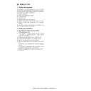
C. Operational descriptions
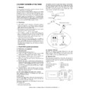
(1) Fusing unit drive
To drive the fusing unit, the drive power is transmitted from the
drive motor (MM) through the connection gear to the upper heat
roller gear.
drive motor (MM) through the connection gear to the upper heat
roller gear.
The drive motor DC brushless motor is driven according to the
control signal sent from the PCU.
control signal sent from the PCU.
(2) Heater lamp drive
The surface temperature of the heat roller detected by the ther-
mistor is sent to the PCU.
mistor is sent to the PCU.
When the temperature is lower than the specified level, the heater
lamp lighting signal is sent from the PCU to the heater lamp drive
circuit in the sub power PWB.
lamp lighting signal is sent from the PCU to the heater lamp drive
circuit in the sub power PWB.
The power triac in the heater lamp drive circuit is turned on, and
the AC power is supplied to the heater lamp, lighting the lamp and
heating the heat roller.
the AC power is supplied to the heater lamp, lighting the lamp and
heating the heat roller.
To prepare for an abnormally high temperature of the heat roller,
the thermostat is provided for safety.
the thermostat is provided for safety.
When the thermostat is opened, power supply (AC line) to the
heater lamp is cut off.
heater lamp is cut off.
(3) Fusing operation
Toner on paper is heated and pressed to be fused by the heat
roller.
roller.
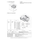
Code
Signal
name
Name
Type
Function/Operation
Active
condition
Note
RTH1
RTH1
Fusing temperature
sensor (1)
sensor (1)
Thermistor Detects the surface temperature of the fusing roller
(heating). (Center section)
Analog input
RTH2
RTH2
Fusing temperature
sensor (2)
sensor (2)
Thermistor Detects the surface temperature of the fusing roller
(heating). (Edge section)
Analog input
HLTS
HLTS
Thermostat (1)
Shuts conduction to the heater lamp when the
temperature rises abnormally. [For the fusing roller
(heating)]
temperature rises abnormally. [For the fusing roller
(heating)]
HL1
HL1
Heater lamp (1)
Heats the fusing roller (heating).
HL2
HL2
Heater lamp (2)
Heats the fusing roller (heating).
MM
MM
Main motor
Drives the fusing unit.
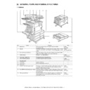
1
Heater lamp 1
Generates heat and transmits heat to the heat roller. The temperature is controlled by the
thermistor. (Temperature control is made mainly on the center.)
thermistor. (Temperature control is made mainly on the center.)
2
Heater lamp 2
Generates heat and transmits heat to the heat roller. The temperature is controlled by the
thermistor. (Temperature control is made mainly on both sides.)
thermistor. (Temperature control is made mainly on both sides.)
3
Upper heat roller
Transmits heat to melt toner on paper and fuse toner by means of a pressure with the lower heat
roller.
roller.
4
Lower heat roller
Fuses toner on paper by means of a pressure with the upper heat roller.
To improve fusing capability, the diameter is greater than the conventional ones.
(ø30mm
To improve fusing capability, the diameter is greater than the conventional ones.
(ø30mm
→
ø40mm)
5
Fusing upper separation pawl
Prevents winding of paper around the upper heat roller.
6
Fusing lower separation pawl
Prevents winding of paper around the lower heat roller.
7
Thermistor (Center)
Detects the surface temperature of the upper heat roller.
(On/off of heater lamp 1 is controlled according to the detected temperature.)
(On/off of heater lamp 1 is controlled according to the detected temperature.)
8
Thermistor (Side)
Detects the surface temperature of the upper heat roller.
(On/off of heater lamp 2 is controlled according to the detected temperature.)
(On/off of heater lamp 2 is controlled according to the detected temperature.)
9
Thermostat
When an abnormal temperature of the upper heat roller is detected, the heater lamp power is
interrupted.
To supply power again, press the switch on the top.
interrupted.
To supply power again, press the switch on the top.
10
Cleaning roller
Cleans toner on the lower heat roller. The blast process is employed.
MM
PCU
Fusing roller (Heating)
HL2
HL1
---------
Fusing roller (Pressing)
Paper exit
AR-M351U/M451U, AR-M355U/M455U MAINTENANCE AND DETAILS OF EACH SECTION 7 - 23
The fusing heat roller (heating) is provided with two heater lamps,
which heat the fusing roller to fuse toner onto paper.
which heat the fusing roller to fuse toner onto paper.
The fusing rollers (pressing) are of silicon rubber because of the
following reasons and purpose.
following reasons and purpose.
1) Paper is separated upward. (Since the fusing roller (heating) is
of higher hardness, the fusing roller (pressing) is deformed to
separate paper upward.)
separate paper upward.)
2) The nip quantity is increased to increase heat capacity for
paper.
3) By pressing paper with the flexible roller, toner is fused without
deformation.
(4) Fusing temperature control
The temperature sensor is provided at the center of the fusing
roller (heating).
roller (heating).
The roller temperature is detected by the installed temperature
sensor, and the heater lamp is controlled so that the temperature
is maintained at the specified level.
sensor, and the heater lamp is controlled so that the temperature
is maintained at the specified level.
In addition, the fusing temperature is switched according to the
kind of paper.
kind of paper.
(5) Cleaning roller
The fusing section cleaning roller of this machine is made of the
blast process.
1) Remaining toner attaches to the upper heat roller.
1) Remaining toner attaches to the upper heat roller.
2) Due to coating and the temperature characteristics of the
upper heat roller, toner is not attached to the upper heat roller
but to the lower heat roller.
but to the lower heat roller.
3) Remaining toner on the lower heat roller is further attached to
the cleaning roller due to the temperature characteristics and
the difference in roughness of surfaces of the rollers.
the difference in roughness of surfaces of the rollers.
4) Remaining toner attached to the cleaning roller is accumulated
until the roller is replaced.
D. Maintenance and parts replacement
(1) Maintenance list
Mode
Fusing roller
AR-M351U/
M355U
AR-M451U/
M455U
Ready condition
print mode
print mode
Plain paper
190°C
190°C
Heavy Paper
190°C
190°C
Postcard
190°C
190°C
Envelope
190°C
190°C
Pre-heat
150°C
150°C
Unit name
No.
Part name
When
calling
100K
200K
300K
400K
500K
600K
700K
800K
Remark
Fusing
section
1
Upper heat roller
✕
✕
▲
✕
▲
✕
▲
✕
▲
2
Lower heat roller
✕
✕
▲
✕
▲
✕
▲
✕
▲
3
Upper separation pawl
❍
❍
▲
❍
▲
❍
▲
❍
▲
4
Lower separation pawl
❍
❍
▲
❍
▲
❍
▲
❍
▲
5
Thermistor
✕
✕
✕
✕
✕
✕
✕
✕
✕
Clean and remove
paper dust.
paper dust.
6
Upper heat roller gear
✕
▲
✕
▲
✕
▲
✕
▲
7
CL roller
✕
✕
▲
✕
▲
✕
▲
✕
▲
8
CL roller bearing
✕
✕
▲
✕
▲
✕
▲
✕
▲
9
Paper guides
❍
❍
❍
❍
❍
❍
❍
❍
❍
10
Gears
✩
✩
✩
✩
✩
✩
✩
✩
5
3
4
1
6
5
8
2
7
8
AR-M351U/M451U, AR-M355U/M455U MAINTENANCE AND DETAILS OF EACH SECTION 7 - 24
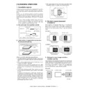
(2) Maintenance and parts replacement
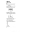
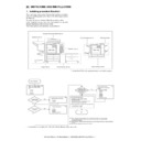
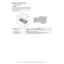
a. Fusing unit
1) Pull out the left door.
2) Remove the stopper R.
3) Pull the fusing lever, and remove the fusing unit.
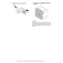
a-1. Lower separation pawl
1) Remove the fusing unit.
2) Open the fusing rear lower PG, and remove the lower separa-
tion pawl.
a-2. Upper separation pawl
1) Remove the fusing unit.
2) Remove the rear upper PG, and remove the upper separation
pawl.
No.
Unit
Parts
a
Fusing unit
1
Lower separation pawl
❍
2
Upper separation pawl
❍
3
Thermistor
✕
4
Lower heat roller
✕
5
CL roller
✕
6
CL roller bearing
✕
7
Heater lamp
8
Upper heat roller
✕
9
Upper heat roller gear
✕
10
Thermostat
a-1
a-3
a-2
a-6
a-3
a-3
a-10
a-4
a-8
a-9
a
a-6
a-5
a-7

