Read Sharp AR-LC4 Specification online
CONTENTS
Parts marked with “
” are important for maintaining the safety of the set. Be sure to replace these parts with
specified ones for maintaining the safety and performance of the set.
SHARP CORPORATION
SERVICE MANUAL
CODE: 00ZARLC4//A1E
LARGE CAPACITY
FEEDER
FEEDER
MODEL
AR-LC4
1. SPECIFICATIONS . . . . . . . . . . . . . . . . . . . . . . . . . . . . . . . . . . . . . . 1-1
2. OUTLINE OF THE MACHINE . . . . . . . . . . . . . . . . . . . . . . . . . . . . . . 2-1
3. GENERAL OPERATION . . . . . . . . . . . . . . . . . . . . . . . . . . . . . . . . . . 3-1
4. DISASSEMBLY AND REPLACEMENT/ADJUSTMENT . . . . . . . . . . 4-1
5. ELECTRIC CIRCUIT . . . . . . . . . . . . . . . . . . . . . . . . . . . . . . . . . . . . . 5-1
6. PREVENTIVE MAINTENANCE . . . . . . . . . . . . . . . . . . . . . . . . . . . . 6-1
7. UNPACKING AND INSTALLATION . . . . . . . . . . . . . . . . . . . . . . . . . 7-1
GENERAL PRECAUTIONS FOR INSTALLATION/SERVICE/
MAINTENANCE FOR LARGE CAPACITY FEEDER AR-LC4
MAINTENANCE FOR LARGE CAPACITY FEEDER AR-LC4
1. When installing the Large Capacity Feeder AR-LC4 to the Copier, be sure to follow the instructions
described in the “Unpacking/Set-Up Procedure for the AR-LC4” booklet which comes with each
unit of the AR-LC4.
2. Installed only by an authorized/qualified person.
3. When transporting/installing the AR-LC4, employ two persons. The AR-LC4 is fairly heavy and weights
approximately 40 kg (89 lb), therefore pay full attention when handling it.
4. Before starting installation, servicing or maintenance work, be sure to turn off and unplug the copier
first.
5. Supplied with power from the copier, requiring no additional power source.
6. Grounded to the specified positions on the machine frame.
7. When serving or maintaining, be careful about the rotating or operating sections such as gears,
pulleys, sprockets, cams, belts, etc.
8. When parts are disassembled, reassembly is basically the reverse of disassembly unless otherwise
noted in this manual or other related documents. Be careful not to reassemble small parts such as
screws, washers, pins, E-rings, toothed washers to the wrong places.
9. Basically, the machine should not be operated with any parts removed or disassembled.
10. Delicate parts for preventing safety hazard problems (such as thermofuses, door switches sensors,
etc. if any) should be handled/installed/adjusted correctly.
11. During servicing or maintenance work, be sure to check the nameplate and other cautionary labels (if
any) to see if they are clean and firmly stuck. If not, take appropriate actions.
12. Use suitable measuring instruments and tools.
13. The PC board must be stored in an anti-electrostatic bag and handled carefully using a wristband,
because the ICs on it may be damaged due to static electricity.
Caution: Before using the wrist band, pull out the power cord plug of the copier and make sure that
there is no uninsulated objects in the vicinity.
14. For the recovery and disposal of used the large capacity feeder, consumable parts, packing materials,
used batteries, and RAM-ICs including litium batteries, it is recommended that the relevant local
regulations/rules.
AR-LC4 CONTENTS
CONTENTS
1. SPECIFICATIONS .........................................................................................
1-1
1.1
Basic specifications ........................................................................................................ 1-1
1.2
Machine specifications ................................................................................................... 1-2
1.3
Electrical specifications .................................................................................................. 1-2
1.4
Environmental conditions ................................................................................................ 1-3
1.5
Conforming standards ..................................................................................................... 1-3
1.6
Others ............................................................................................................................. 1-3
2. OUTLINE OF THE MACHINE ........................................................................
2-1
2.1
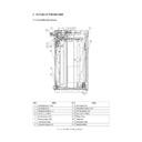
Front Sectional View ....................................................................................................... 2-1
2.2
Electrical Parts Layout .................................................................................................... 2-2
2.3
Electrical Parts ............................................................................................................... 2-3
3. GENERAL OPERATION ................................................................................
3-1
3.1
Description of Operation ................................................................................................. 3-1
3.2
Error Detection ................................................................................................................ 3-2
3.3
Flow Chart ...................................................................................................................... 3-3
3.4
Timing Chart ................................................................................................................... 3-5
4. DISASSEMBLY AND REPLACEMENT/ADJUSTMENT ...............................
4-1
4.1
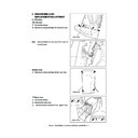
Covers ............................................................................................................................ 4-1
4.2
Tray Unit ......................................................................................................................... 4-2
4.3
Feed Unit ........................................................................................................................ 4-3
4.4
Electric Parts .................................................................................................................. 4-4
4.5
Rollers ............................................................................................................................ 4-6
4.6
Side Guides / End Guide ................................................................................................ 4-7
4.7
Tray Wire ......................................................................................................................... 4-8
4.8
Sidewise Deviation Adjustment ..................................................................................... 4-11
4.9
Stopper Adjustment ...................................................................................................... 4-11
5. ELECTRICAL CIRCUIT .................................................................................
5-1
5.1
Harness Diagram ............................................................................................................ 5-1
5.2
Circuit Diagram ............................................................................................................... 5-2
5.3
PC Board ........................................................................................................................ 5-5
6. PREVENTIVE MAINTENANCE ....................................................................
6-1
7. UNPACKING AND INSTALLATION................................................................
7-1
AR-LC4 SPECIFICATIONS 1 - 1
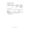
1. SPECIFICATIONS
1.1
Basic specifications
a. General
b. Case
c. Paper feed
Kind
Large capacity paper feed unit (size fixed)
Installation type
Floor type, field option
Installing position
Right side of the copier (Paper feed side)
Fixing type
Latch system (Fixed with the exclusive-use bracket on the upper side of the
PPC paper feed side.)
PPC paper feed side.)
Release type
Latch release, parallel shift system by the handle
Case structure
Frame assembly, box structure
Paper feed type
Pick-up roller drop and paper feed roller type
Separation type
Drive separation roller type
Transport reference
Center reference
Tray
section
section
Capacity
4,000 sheets (Load
height 428mm or
less)
height 428mm or
less)
(Capacity reference value)
64g paper 4,500 sheets
Under normal temperature and normal
humidity, immediately after unpacking
64g paper 4,500 sheets
Under normal temperature and normal
humidity, immediately after unpacking
Remaining
quantity display
quantity display
Calculated from tray-up time.
Displayed graphically in 4-step on the control panel of PPC.
Displayed graphically in 4-step on the control panel of PPC.
Paper supply
method
method
Front loading system
(The paper loading section at the front is pulled out and paper is
loaded from above of the paper loading section.)
(The paper loading section at the front is pulled out and paper is
loaded from above of the paper loading section.)
Jam process
method
method
LCF is separated from the machine and jam paper is removed.
Size change
Inhibited
However, size change from A4/B5 to LT is allowed by a serviceman.
However, size change from A4/B5 to LT is allowed by a serviceman.
Size display
Not provided
Applicable
paper
paper
Size
Fixed sizes only
• For B5, installation of the exclusive-use end
plate is required.
• The exclusive-use end plate for B5 is not
included in the package.
A series: A4, B5
LT series: LT
Kinds
PPC paper (Static frictional coefficient between paper: 0.6 or less)
(Note) Tracing paper, OHP films, labels, postcards cannot be used.
(Note) Tracing paper, OHP films, labels, postcards cannot be used.
Weight
64 to 209g paper
(17lbs (Pond paper) to 110lbs (index))
(17lbs (Pond paper) to 110lbs (index))

