Read Sharp AR-C270 (serv.man9) Service Manual online
ADJ M8
Photoconductor phase adjustment
This adjustment is available in two procedures, old and new. Both are
basically the same. Either procedure will do.
basically the same. Either procedure will do.
The differences between the old and the new procedures are as fol-
lows:
lows:
∗
Some AR-C100/C150 machines use the old procedure (with SIM
44-20). On the other hand, the AR-C250/C160/C270 uses only the
new procedure (with SIM 44-31) and does not have the old
procedure.
In the AR-C100/C150, the old procedure (with SIM 44-20) is
abolished and the new procedure is employed in the middle of
production.
44-20). On the other hand, the AR-C250/C160/C270 uses only the
new procedure (with SIM 44-31) and does not have the old
procedure.
In the AR-C100/C150, the old procedure (with SIM 44-20) is
abolished and the new procedure is employed in the middle of
production.
∗
In SIM 44-31, the adjustment pattern is printed in A4R or 8.5"
×
11"R size.
In SIM 44-20, the adjustment pattern is printed in A3 or 11"
In SIM 44-20, the adjustment pattern is printed in A3 or 11"
×
17"
size.
∗
The adjustment pattern photoconductor phase adjustment pitch
(interval) differs. (12 division
(interval) differs. (12 division
→
8 division)
This adjustment is required in the following cases:
•
When the photoconductor drum is replaced.
•
When the photoconductor drum is removed from the machine.
•
When the photoconductor drum drive section is disassembled.
•
When the photoconductor drum drive unit is replaced.
•
When U2 trouble occurs.
•
When PCU MAI PWB is replaced.
•
When EEPROM on the PCU MAIN PWB is replaced.
Old procedure of photoconductor phase adjustment (SIM
44-20)
44-20)
1) Enter the SIM 44-20 mode.
2) Enter "2" in the setup item A (PRINT MODE) with the 10-key, then
press the [OK] key. (Default setting is 3.)
3) Select the paper feed cassette with A3 (11"
×
17") paper in the
setup item E (PAPER SELECT), and press the [OK] key.
∗
Use the paper tray at the bottom.
4) Press the [EXECUTE] key, and the drum deflection adjustment
pattern is printed in four pages.
∗
Pattern N (1, 4, 7, 10) is printed.
5) Check the deflection cycle of 125.6mm pitch of four printed pat-
terns (C, M, Y). Use the output pattern of the smallest deflection
as the set value of each color, and set it to item B, C, and D. (After
entering the adjustment value, press the OK key.)
as the set value of each color, and set it to item B, C, and D. (After
entering the adjustment value, press the OK key.)
6) After entering the adjustment value, enter "3" to set item A with
the 10-key and press the [EXECUTE] key to print the adjustment
pattern again.
pattern again.
If the above procedures cannot bring a satisfactory result, select
mode 1 and print twelve pages of the print pattern.
This allows to make more detailed checks and adjustments.
The adjustment procedure is the same as procedure 5).
It, however, takes about 6 min to do this procedure.
mode 1 and print twelve pages of the print pattern.
This allows to make more detailed checks and adjustments.
The adjustment procedure is the same as procedure 5).
It, however, takes about 6 min to do this procedure.
NOTE: If there is an extra deflection other than the drum frequency
(125.6mm pitch), check the set values of the RS motor and
the fusing motor speed.
the fusing motor speed.
7 – 8
New procedure of photoconductor phase adjustment
(SIM 44-31)
(SIM 44-31)
1) Enter the SIM 44-31 mode.
2) Enter "2" in the setup item A (PRINT MODE) with the 10-key, and
press the [OK] key. (The default is "3.")
3) Select the paper tray with A4R (8.5
×
11R) paper in the setup item
E (PAPER SELECT) and press the [OK] key.
NOTE: Use the lowest paper tray.
4) Press the [EXECUTE] key, and the drum deflection adjustment
patterns (4 pages) are printed.
* Pattern numbers 1, 3, 5, and 7 are printed on the output pattern.
5) Check the deflection of 125.6mm pitch for each of C, M, and Y in
the four output patterns, and select the output pattern number with
the smallest deflection as the set value of each color, and set the
number to each of setup items B, C, and D. (After entering the ad-
justment value, press the [OK] key.)
the smallest deflection as the set value of each color, and set the
number to each of setup items B, C, and D. (After entering the ad-
justment value, press the [OK] key.)
6) After entering the adjustment value, enter "3" in the setup item A
with the 10-key and press the [EXECUTE] key to print an adjust-
ment pattern for checking again.
ment pattern for checking again.
If the above procedure is not satisfactory, select the PRINT MODE 1
to print 12 print patterns.
This allows to make more detailed check and adjustment. The adjust-
ment procedure is the same as procedure 5).
This procedure takes about 4 minutes.
to print 12 print patterns.
This allows to make more detailed check and adjustment. The adjust-
ment procedure is the same as procedure 5).
This procedure takes about 4 minutes.
NOTE: If there is an extra deflection other than the drum frequency
(125.6mm pitch), check the set values of the RS motor and
the fusing motor speed.
the fusing motor speed.
ADJ M9A
Image resist adjustment (Auto
adjustment) (AR-C250/C160/C270)
(New version of AR-C150)
adjustment) (AR-C250/C160/C270)
(New version of AR-C150)
The following items are automatically adjusted.
•
ADJ M9/ADJ1 main scanning direction copy magnification ratio ad-
justment (Scanner (writing) unit) (Black)
justment (Scanner (writing) unit) (Black)
•
ADJ M9/ADJ 2 main scanning direction image magnification ratio
adjustment, image resist adjustment (Scanner (writing) unit)
(Color)
adjustment, image resist adjustment (Scanner (writing) unit)
(Color)
•
ADJ M10 sub scanning direction image resist adjustment (Scanner
(writing) unit)
(writing) unit)
If this automatic adjustment of ADJ M9A is not satisfactory, perform
the manual adjustment of ADJ M9 and ADJ M10.
the manual adjustment of ADJ M9 and ADJ M10.
This adjustment is required in the following cases:
•
When the scanner (writing) unit is replaced.
•
When the scanner (writing) unit is removed from the machine.
•
When the main scanning direction image magnification ratio ad-
justment (scanner (writing) unit) (Black) is performed.
justment (scanner (writing) unit) (Black) is performed.
•
When color image mis-resist is generated in the main scanning di-
rection.
rection.
•
When color image mis-resist is generated in the sub scanning di-
rection.
rection.
•
When installation or the installing place is changed.
•
When U2 trouble occurs.
•
When ICU MAIN PWB is replaced.
•
When EEPROM on ICU MAIN PWB is replaced.
Note before adjustment
Before execution of this adjustment, check that the following adjust-
ment have been properly completed.
ment have been properly completed.
∗
Photoconductor phase adjustment (ADJ M8)
∗
Image skew adjustment (scanner (writing) unit) (ADJ M7)
1) Enter the SIM 50-22 mode.
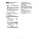
125mm
125mm
125mm
Chec
k the deflection of 125mm pitch.
Deflection pattern of Magenta
A4R (8.5 x 11R)
7 – 9
3) Check the following items with the check pattern.
∗
Check that the section of the greatest density of C and M in
MSR check pattern, MSF check pattern 1, and SS check pat-
tern is in the range of
MSR check pattern, MSF check pattern 1, and SS check pat-
tern is in the range of
±
1 with the black triangle mark as the
center reference.
If this check is difficult, perform the following procedure.
Check that the print lines of M and C in SS check pattern 2,
MSF check pattern 2, and MSR check pattern 2 coincide with
the print lines of K.
If this check is difficult, perform the following procedure.
Check that the print lines of M and C in SS check pattern 2,
MSF check pattern 2, and MSR check pattern 2 coincide with
the print lines of K.
∗
Check that the print line of Y in the check (adjustment) pattern
of MSR check pattern 2, MSF check pattern 2, and SS check
pattern 2 coincides with the print line of K.
of MSR check pattern 2, MSF check pattern 2, and SS check
pattern 2 coincides with the print line of K.
If the above conditions are satisfied, cancel the simulation and termi-
nate the adjustment.
nate the adjustment.
If the above conditions are not satisfied, perform the following proce-
dures.
dures.
4) Set the printed check (adjustment) pattern on the document table.
At that time, adjust so that the white triangle mark comes to the
center of the left side of the document table, and place 5 sheets of
white paper on it.
Check that the check (adjustment) pattern is in close contact with
the document table.
center of the left side of the document table, and place 5 sheets of
white paper on it.
Check that the check (adjustment) pattern is in close contact with
the document table.
5) Press the [EXECUTE] key.
The check (adjustment) pattern is scanned (read) and the image
resist adjustment is automatically performed. (It takes about 30
sec for scanning (reading) and calculation.)
resist adjustment is automatically performed. (It takes about 30
sec for scanning (reading) and calculation.)
The calculated adjustment value is displayed together with the adjust-
ment result (EXACT, ROUGH, ERROR).
ment result (EXACT, ROUGH, ERROR).
EXACT: The adjustment has been normally completed.
ROUGH: The accuracy of the adjustment is lower than EXACT due
to dirt, dusts, and improper placing of the check
(adjustment) pattern, etc.
(adjustment) pattern, etc.
ERROR: Adjustment error due to erroneous scanning
When "ERROR" is displayed, check the following items and repeat
procedures from procedure 1 or perform the manual adjustment of
image resist (ADJ M9/ADJ 1/ADJ 2).
procedures from procedure 1 or perform the manual adjustment of
image resist (ADJ M9/ADJ 1/ADJ 2).
∗
The paper is not placed properly.
∗
Dirt and dust on the glass and mirrors.
∗
The check (adjustment) pattern is dirty, folded, or not in close
contact with the document glass.
contact with the document glass.
When the check (adjustment) pattern is normally scanned (read), the
image resist adjustment is automatically performed and EXACT or
ROUGH is displayed, go to procedure 6).
image resist adjustment is automatically performed and EXACT or
ROUGH is displayed, go to procedure 6).
6) Press the [EXECUTE] key.
A4 or 8.5
×
11 paper is automatically selected and a check (ad-
justment) pattern is printed.
7) Perform the same procedure as procedure 3). If the image resist
is within the specified range, adjustment is completed.
If the adjustment is repeated twice and the image resist is not within
the specified range, perform the manual adjustment of image resist
(ADJ M9/ADJ 1/ADJ 2).
the specified range, perform the manual adjustment of image resist
(ADJ M9/ADJ 1/ADJ 2).
If the image resist adjustment (auto) has been satisfactorily com-
pleted with SIM 50-22, there is no need to perform the following pro-
cedures.
pleted with SIM 50-22, there is no need to perform the following pro-
cedures.
1) ADJ M9 (Main scanning direction image resist adjustment/Main
scanning direction image magnification ratio adjustment) SIM 50-
20
20
2) ADJ M10 (Sub scanning direction image resist adjustment) SIM
50-21
ADJ M9
Main scanning direction copy
magnification ratio adjustment
(Manual adjustment) (Scanner
(Writing) unit)
Main scanning direction image
registration adjustment (Manual
adjustment) (Scanner (Writing) unit)
magnification ratio adjustment
(Manual adjustment) (Scanner
(Writing) unit)
Main scanning direction image
registration adjustment (Manual
adjustment) (Scanner (Writing) unit)
ADJ 1
Main scanning direction copy
magnification ratio adjustment (Scanner
(Writing) unit) (Black)
magnification ratio adjustment (Scanner
(Writing) unit) (Black)
This adjustment must be performed in the following cases:
•
When the black scanner (writing) unit is replaced.
•
When a U2 trouble occurs.
•
When the ICU main PWB is replaced.
•
When the EEPROM of the ICU main PWB is replaced.
1) Enter the SIM 50-10 mode.
2) Select H: BLACK LD MAG.
3) Press the [EXECUTE] key.
4) Check that the dimension inside the printed half tone pattern is
220mm.
Use one of the following paper sizes (A4/A3/11"
×
8.5"/11"
×
17")
5) If the dimension is not as specified above, change the set value
and perform an adjustment again.
Enter the adjustment value with the 10-key and press the [OK]
key.
Enter the adjustment value with the 10-key and press the [OK]
key.
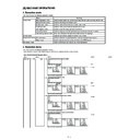
Check (adjust) pattern
220mm
7 – 10
ADJ 2
Main scanning direction color image
registration adjustment (Scanner
(Writing) unit) (Color)
Main scanning direction copy
magnification ratio adjustment (Scanner
(Writing) unit) (Color)
registration adjustment (Scanner
(Writing) unit) (Color)
Main scanning direction copy
magnification ratio adjustment (Scanner
(Writing) unit) (Color)
This adjustment must be performed in the following cases:
•
When the scanner (writing) unit is replaced.
•
When the scanner (writing) unit is removed from the machine.
•
When the main scanning direction image magnification ratio (scan-
ner (writing) unit (Black)) is performed.
ner (writing) unit (Black)) is performed.
•
When a color image mis-resist occurs in the main scanning direc-
tion.
tion.
•
When the installing position is changed.
•
When a U2 trouble occurs.
•
When the ICU main PWB is replaced.
•
When the EEPROM of the ICU main PWB is replaced.
1) Enter the SIM 50-20 mode.
2) Select the paper feed cassette of A3 (11"
×
17") paper in the setup
item H (PAPER SEL).
∗
Use the paper tray at the bottom.
3) Press the [EXECUTE] key. The adjustment pattern is printed.
4) Check the print patterns of the rough adjustment and the fine ad-
justment for equal color on the front and the rear side.
Rough adjustment print pattern check: Check that the rough ad-
justment print pattern is at the center for the rough adjustment ref-
erence pattern.
Fine adjustment print pattern check: Check that the fine adjust-
ment print pattern is at the center for the fine adjustment reference
pattern.
(If the fine adjustment print pattern is in the range of 0
±
1 for the
scale of the fine adjustment reference pattern, there is no need to
adjust.)
adjust.)
∗
A: Rough adjustment pattern
∗
B: Fine adjustment pattern
∗
C: Adjustment range (0
±
1)
7 – 11

