Read Sharp AR-C270 (serv.man6) Service Manual online
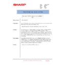
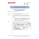
[5] EXTERNAL VIEW AND INTERNAL STRUCTURE
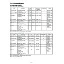
B. Internal parts
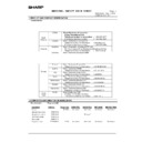
(1) Cross section
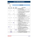
No.
Parts
Note
Name
Function and operation
1
No. 2 mirror
Sends the original image to No. 3 mirror.
2
No. 3 mirror
Send the original image to the CCD.
3
Y-LSU unit
Converts yellow components of image signals sent from the ICU PWB into laser
beams, and radiates the beams onto the OPC drum.
beams, and radiates the beams onto the OPC drum.
4
M-LSU unit
Converts magenta components of image signals sent from the ICU PWB into laser
beams, and radiates the beams onto the OPC drum.
beams, and radiates the beams onto the OPC drum.
5
No. 1 mirror
Sends the original image to No. 2 mirror.
6
Scanner lamp
Radiates light to the CCD for scanning the original image.
7
CCD lens
Reduces the original image (light) and project it to the CCD.
8
C-LSU unit
Converts cyan components of image signals sent from the ICU PWB into laser
beams, and radiates the beams onto the OPC drum.
beams, and radiates the beams onto the OPC drum.
9
CCD PWB
Reads the original image and converts it into electrical signals.
10
K-LSU unit
Converts black components of image signals sent from the ICU PWB into laser
beams, and radiates the beams onto the OPC drum.
beams, and radiates the beams onto the OPC drum.
11
Developing roller (Y)
Attaches toner on the OPC drum. (Y)
12
Developing roller (M)
Attaches toner on the OPC drum. (M)
13
Developing roller (C)
Attaches toner on the OPC drum. (C)
14
Developing roller (K)
Attaches toner on the OPC drum. (K)
15
Upper resist roller
Transports paper to the transfer section.
16
Lower resist roller
Transports paper to the transfer section.
17
Paper transport roller 1
Transports paper to the transfer resist roller.
18
Idle roller
Applies pressure to paper and the transport roller.
19
Idle roller
Prevents against paper skew.
20
Paper transport roller 1
Transports paper to the transfer section (transfer resist roller).
21
Paper feed tray (No. 1 paper tray)
Feeds paper to the paper transport section.
22
Separation roller (No. 1 paper tray)
Separates paper and transport it to the paper transport section.
1 2
3 4
5
6
7
8
9
11
12
13
14
15
16
12
13
14
15
16
17
18
18
19
20
21
22
23
24
25
26
27
28
29
30
22
23
24
25
26
27
28
29
30
31
33
34
34
37
39
40
41
42
43
44
45
46
47
48
49
67
51
52
53
54
55
56
57
58
59
60
35
32
36
61
62
63
64
65
66
10
38
50
68
75
70
69
72
71
73
74
76
77
5 – 4A
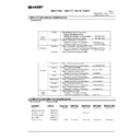
No.
Parts
Note
Name
Function and operation
23
Paper pickup roller (No. 1 paper tray)
Sends paper to the paper feed roller.
24
Idle roller
Applies pressure to paper and the transport roller.
25
Paper transport roller 2
Transports paper to the transport roller 1.
26
Paper feed roller (No. 2 paper roller)
Feeds paper to the paper transport section.
27
Separation roller (No. 2 paper tray)
Separates paper and prevents against double feed.
28
Paper pickup roller (No. 2 paper tray)
Sends paper to the paper feed roller.
29
Idle roller
Applies pressure to paper and the transport roller.
30
Paper transport roller 3
Transports paper to the transport roller 2.
31
Paper feed roller (No. 3 paper tray)
Feeds paper to the paper transport section.
32
Separation roller (No. 3 paper tray)
Separates paper and prevents against double feed.
33
Paper pickup roller (No. 3 paper tray)
Feeds paper to the paper feed roller.
34
Idle roller
Applies pressure to paper and the transport roller.
35
Paper transport roller 4
Transports paper to the transport roller 3.
36
Paper feed roller (No. 4 paper tray)
Feeds paper to the paper transport section.
37
Separation roller (No. 4 paper tray)
Separates paper and prevents against double feed.
38
Paper pickup roller (No. 4 paper tray)
Sends paper to the paper feed roller.
39
Transfer roller (K)
Applies a transfer voltage to the transfer belt.
40
OPC drum unit (K)
Forms black latent electrostatic images.
41
Main charger unit (K)
Charges the black OPC drum negatively.
42
OPC drum unit (C)
Forms cyan latent electrostatic images.
43
Transfer roller (C)
Applies a transfer voltage to the transfer belt.
44
Main charger unit (C)
Charges the cyan OPC drum negatively.
45
OPC drum unit (M)
Forms magenta latent electrostatic images.
46
Transfer roller (M)
Applies a transfer voltage to the transfer belt.
47
Main charger unit (M)
Charges the magenta OPC drum negatively.
48
OPC drum unit (Y)
Forms yellow latent electrostatic images.
49
Transfer roller (Y)
Applies a transfer voltage to the transfer belt.
50
Main charger unit (Y)
Charges the yellow OPC drum negatively.
51
Transfer belt
Transfers toner images on the OPC drum to paper.
52
Waste toner bottle
Collects waste toner.
53
Oil tank
Stores oil.
54
Lower heater lamp
Heats the lower heat roller.
55
Lower heat roller
Applies a pressure and heat to toner and fuses it to paper.
56
Lower separation pawl
Separates paper mechanically from the lower heat roller.
57
Fusing transport roller
Transports paper to the paper exit roller.
58
ADU gate
Switches the paper route in the duplex mode.
59
Paper exit roller
Discharges paper outside the machine.
60
Idle roller
Applies pressure to paper and the paper exit roller.
61
Idle roller
Applies pressure to paper and the transport roller.
62
Upper cleaning roller
Cleans the fusing roller.
63
Upper heat roller
Applies a pressure and heat to toner and fuses it to paper.
64
Upper heat lamp
Heats the upper heat roller.
65
Oil roller
Applies oil to the upper heat roller.
66
Oil blade
Controls oil quantity on the oil roller to be even.
67
Separation pawl
Separates paper from the transfer belt mechanically.
Japan only
68
Waste toner bottle
Collects waste toner from transfer belt.
69
Paper pickup roller
Sends paper to the paper feed roller.
Manual paper
feed section
feed section
70
Paper pickup solenoid
Presses paper onto the paper pickup roller.
71
Manual paper feed roller
Feeds paper to the paper transport section.
72
Manual paper feed clutch
Transmits the paper feed drive motor power to the manual paper feed unit.
(Controls ON/OFF of the manual paper feed unit.)
(Controls ON/OFF of the manual paper feed unit.)
73
Separation roller
Separates paper to prevent against double feed.
74
Manual transport roller
Applies a pressure to paper and the transport roller to give the transport roller
power to the paper.
power to the paper.
75
Idle roller
Applies a pressure to paper and the transport roller and gives a transport power of
the transport roller to the paper.
the transport roller to the paper.
76
Resist roller cleaner
Clean the resist roller.
AR-C160/C270
5 – 5A
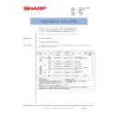
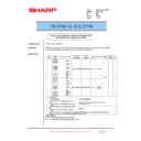
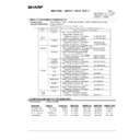
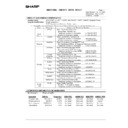
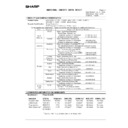
f. Transfer section
No.
Parts
Model
Note
Code
Signal
name
Name
Type
Function/Operation
Active
condition
1
Transfer unit
Transfers toner from the OPC
drum to paper.
drum to paper.
2
Transfer belt
separation pawl
separation pawl
Separates paper from the
transfer belt mechanically.
transfer belt mechanically.
Japan only
3
BPSS
BPSS
Separation pawl
solenoid
solenoid
Drives the separation
solenoid.
solenoid.
Japan only
4
Transfer belt
drive roller
drive roller
Drives the transfer belt.
5
Transfer
discharge
electrode
discharge
electrode
Discharges electric charges
of the transfer belt.
of the transfer belt.
4 pcs (Y, M, C,
K)
K)
6
Transfer roller
Applies a transfer voltage to
the transfer belt.
the transfer belt.
4 pcs (Y, M, C,
K)
K)
7
Lift cam
Transmits the transfer belt lift
motor power to the transfer
unit.
motor power to the transfer
unit.
Lifted up in
color print
mode, and lifted
down in
monochrome
mode.
color print
mode, and lifted
down in
monochrome
mode.
8
PCS
PCS
Image density
sensor
sensor
Photo sensor
(Photo reflection)
(Photo reflection)
Detects toner patch density in
image density correction.
image density correction.
Analog input
9
BLUM
BLUM
Transfer belt
motor
motor
Stepping motor
Lifts the transfer belt unit.
1
2
3
4
5
6
7
8
9
10
11
12
15
16
18
19
20
21
22
13
14
16
10
8
12
15
5
6
4
3
2
7
5
5
5
6
6
6
23
24
25
26
27
14
13
28
28
5 – 6A

