Read Sharp AR-C270 (serv.man15) Service Manual online
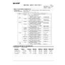
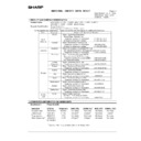
[11] MAINTENANCE AND DISASSEMBLY/ASSEMBLY
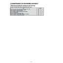
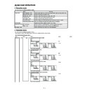
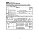
1. Necessary procedure for maintenance and servicing
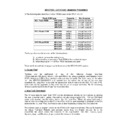
(1) Items to be performed before maintenance servicing 1
Item
Simulation
Check the print counter value of each section in each operation mode.
22
1
Check the number of times of paper jams and troubles.
22
2
22
3
22
12
22
4
Prints the list of setups and adjustment values.
22
6
Check the number of use of the RADF, the sorter and the scanner.
22
8
Check the number of use of paper feed sections.
22
9
11 – 1
No
1
2
3
4
5
6
7
8
9
10
11
22 (Auto)/
20 (Manual)
22 (Auto)/
21 (Manual)
ADJ M9A
(ADJ M9)
ADJ M8
ADJ M7
ADJ M6
ADJ M5
ADJ M3
ADJ M9A
(ADJ M10)
JOB No
Work item
Simulation
When
installing
Repair (When a consumable part is replaced)/maintenance
After replacing
OPC drum (
∗
1)
After replacing
developer (
∗
2)
After replacing
transfer belt
After disposing
transfer section
waste toner
After cleaning
scanner
(reading) section
When in
periodic
maintenance
When in
repair/check
(without replacing
consumable parts)
Toner concentration reference control level setup
Developer counter clear
OPC drum counter clear
Image density sensor adjustment
Image density sensor position adjustment
Image skew adjustment
OPC drum phase adjustment
Transfer section waste toner counter clear
Half-tone correction level is set to zero.
Main scan direction image resist adjustment
Sub scan direction image resist adjustment
25
24
24
44
44
64
44
24
44
50
50
(2) Necessar
y w
ork items in maintenance ser
vice
The w
o
rk
items necessar
y f
or maintenance are sho
wn belo
w
.
P
erf
or
m the w
o
rk
according to the f
ollo
wing descr
iption when other than maintenance (when replacing a consumab
le par
t/when repa
ir
ing and chec
king (without replacement of consumab
le par
ts)/
when installing/when cleaning the scanner (reading) section/etc.)
Job No
. indicates the title n
umber of adjustment items specified in the chapter of the adjustments
. Ref
er to Use this n
umber wh
en ref
err
ing to the details
, as necessar
y.
When the de
v
eloper counter is cleared (SIM 24-5) and the OPC dr
um counter is cleared (SIM 24-7), the image density correction (
process correction) is automatically perf
or
med.
2
5
7
13
23
1
20 (Old)/31 (New)
8
27
∗
∗
∗
∗
∗
∗ ∗
∗
∗ ∗
∗
∗
∗
12
ADJ M17
Copy quality adjustment
∗
∗
∗
∗
11 – 2
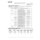
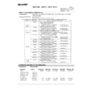
(3) Items to be performed after maintenance servicing 3
Item
Simulation
Paper jam, trouble data clear
24
1
Each paper feed section use number counter clear
24
2
RADF, sorter, scanner use number counter clear
24
3
Maintenance counter clear
24
4
Setup and adjustment data output
22
6
(4) Maintenance display
When the maintenance timing is reached, the following display is shown.
MAINTENANCE REQUIRED CODE: XX
The above two-digit code indicates the kind and the count of the maintenance counter.
The meaning of the CODE indication is as shown below.
CODE (XX) 1st digit
Meaning
A
5K
Maintenance counter value set with SIM 21-1.
B
10K
C
15K
D
20K
E
40K
F
80K
CODE (XX) 2nd digit
Meaning
T
The total maintenance counter has reached the value set with SIM 21-1.
C
The color maintenance counter has reached the value set with SIM 21-1.
A
Both the total maintenance counter and the color maintenance counter have reached the values set with SIM 21-1.
After completion of maintenance, reset this display with SIM 24-4.
11 – 3
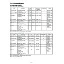
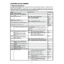
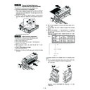
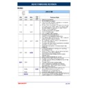
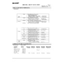
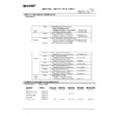
2. List
•
OIL/GRE (Lubricate, grease); CLN (Cleaning); ADJ (Adjustment); REP (Replacement, installation); CP (Change position); CHK (Check); (Clean,
replace, lubricate, grease as necessary); ABL (Disassembly, assembly)
replace, lubricate, grease as necessary); ABL (Disassembly, assembly)
S01
External fitting section
Unit
Part
JOB
CODE
Every
service
call
40K
80K
120K
160K
200K
240K
280K
320K
Remark
U No.
Unit name
P No.
Part name
P01
Original cover
ABL
CLN
∗
∗
∗
∗
∗
∗
∗
∗
∗
P02
Rear cabinet upper
ABL
P03
Rear cabinet lower
ABL
P04
Front cabinet
ABL
P05
Glass holder right
ABL
P06
Glass holder left
ABL
P07
Table glass
CLN
∗
∗
∗
∗
∗
∗
∗
∗
∗
ABL
P08
Shading glass
CLN
∗
∗
∗
∗
∗
∗
∗
∗
∗
ABL
P09
Upper cabinet right
ABL
P10
Upper cabinet left
ABL
P11
Right cabinet upper
ABL
P12
Right cabinet lower rear
ABL
P13
Right cabinet lower front
ABL
P14
Right cabinet lower front
ABL
P15
Left cabinet upper
ABL
P16
Left cabinet lower
ABL
S01/P01/CLN
S01/P02
S01/P03
S01/P04
S01/P05
S01/P06/CLN
S01/P07/CLN
S01/P09
S01/P10
S01/P11
S01/P12
S01/P15
S01/P16
S01/P13
S01/P14
S01/P08/CLN
S01/Ua01
11 – 4

