Read Sharp AR-C270 (serv.man10) Service Manual online
ADJ M11
Image distortion adjustment
This adjustment must be performed in the following cases:
•
When the scanner (reading) section is disassembled.
•
When a copy image distortion occurs.
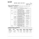
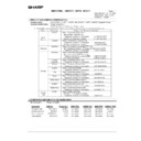
ADJ 1
Scanner (Reading) unit parallelism
adjustment
adjustment
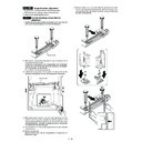
1) Loosen the screw which is fixing the scanner unit A and the drive
wire, and remove the scanner unit A from the drive wire.
2) Manually turn the scanner drive gear to bring the scanner unit B
into contact with the stopper.
At that time, if the scanner unit B makes contact with the two stop-
pers on the front and the rear frame simultaneously, the parallel-
ism of the scanner unit B is proper.
If not, perform the following procedures.
At that time, if the scanner unit B makes contact with the two stop-
pers on the front and the rear frame simultaneously, the parallel-
ism of the scanner unit B is proper.
If not, perform the following procedures.
3) Loosen the fixing screw of the scanner unit drive pulley on the
side where the scanner unit B is not in contact with the stopper.
4) While keeping the scanner unit drive shaft stationary, turn the
scanner unit drive pulley manually so that the scanner unit B
makes contacts with two stoppers on the front and the rear frame
side simultaneously. (Change the relative positions of the scanner
unit drive pulley and the drive shaft.)
makes contacts with two stoppers on the front and the rear frame
side simultaneously. (Change the relative positions of the scanner
unit drive pulley and the drive shaft.)
5) Fix the scanner unit drive pulley fixing screw which was loosened
in procedure 3).
6) Perform procedure 2).
Repeat procedures 3) – 6) until the parallelism of the scanner unit
B becomes proper.
B becomes proper.
7) With the scanner unit B in contact with two stoppers on the front
and the rear frame side simultaneously, slide the scanner unit A
until it comes to the right end of the frame, and fix it to the drive
wire with the fixing screw.
until it comes to the right end of the frame, and fix it to the drive
wire with the fixing screw.
Scanner unit A
Scanner unit B
7 – 18
ADJ 2
Image sub scanning direction distortion
adjustment
adjustment
1) Make a test chart on A3 (11
×
17") paper as shown below. (Draw
a rectangular with four right angles.)
2) Set the test chart made in procedure 1) on the document table.
(Leave a space of about 30mm between the reference position
and the test chart. With the document cover open, make a copy
on A3 (11
and the test chart. With the document cover open, make a copy
on A3 (11
×
17").
3) Check for distortion in the sub scanning direction.
If La = Lb, there is no distortion.
If there is some distortion in the sub scanning direction, perform the
following procedures.
following procedures.
4) Loosen either of two fixing screws of the scanner unit drive pulley.
(Either one on the front or the rear side will do.)
5) With the scanner unit drive shaft kept stationary, turn the scanner
unit drive pulley manually to change the parallelism of scanner
units A and B. (Change the relative positions of the scanner unit
drive pulley and the drive shaft.)
units A and B. (Change the relative positions of the scanner unit
drive pulley and the drive shaft.)
6) Tighten the scanner unit drive pulley fixing screw.
Repeat procedures 2) – 6) until the condition of procedure 3) is
satisfied.
satisfied.
ADJ 3
Image scanning direction distortion
adjustment
adjustment
1) Make a test chart on A3 (11
×
17") paper as shown below. (Draw
a rectangle with four right angles.)
2) Set the test chart made in procedure 1) on the document table.
With the document cover open, make a copy on A3 (11
×
17").
3) Check for distortion in the main scanning direction.
If the four angles of the rectangle on the copy are right angles,
there is no distortion. (Completion of the adjustment)
there is no distortion. (Completion of the adjustment)
If there is some distortion in the main scanning direction, perform the
following procedures
following procedures
4) Check for a difference between the right distortion and the left dis-
tortion (balance).
If Lc = Ld, there is no difference between the left distortion and the
right distortion.
right distortion.
If the above condition is satisfied, go to procedure 6).
If the above condition is not satisfied, perform the following proce-
dures.
If the above condition is not satisfied, perform the following proce-
dures.
Lc
Ld
Lc
Ld
Copy A
Copy B
Left distortion is equal
to right distortion.
to right distortion.
Lc = Ld
Left distortion is not equal
to right distortion
Lc
to right distortion
Lc
≠
Ld
7 – 19
5) Change the height balance of the front frame side scanner rail.
Perform procedures 2) – 5) until there is no difference between
the left distortion and the right distortion.
the left distortion and the right distortion.
6) When there is no difference between the left distortion and the
right distortion, change the height of the scanner rail on the front
frame side.
frame side.
7) Set the test chart made in procedure 1) on the document table,
and make a copy on A3 (11
×
17") paper. Check that the main
scanning distortion is within the specified range.
Repeat procedures 6) – 7) until the main scanning direction distor-
tion is within the specified range.
Repeat procedures 6) – 7) until the main scanning direction distor-
tion is within the specified range.
ADJ M12
Image focus (main scanning direction
copy magnification ratio) adjustment
(CCD position adjustment)
copy magnification ratio) adjustment
(CCD position adjustment)
This adjustment must be performed in the following cases:
•
When the CCD unit is removed from the machine.
•
When the CCD unit is replaced.
•
When the copy image focus is improper.
•
When the copy magnification ratio in the main scanning direction is
improper.
improper.
1) Enter the SIM 48-1 mode.
2) Set the set item B to 50 (initial value).
3) As shown in the figure below, place a scale on the original table.
4) Make a normal copy on A4 paper.
5) Compare the scale image length and the actual scale length.
6) Obtain the main scanning direction copy magnification ratio ac-
cording to the following formula.
Main scanning direction copy magnification ratio
=
(
Original length – Copy length
)
Original length
×
100 [%]
(Example) Fit 10mm of the scale with 10mm of the copied scale and
compare them.
Main scanning direction copy magnification ration
Main scanning direction copy magnification ration
=
100 – 99
100
×
100 = 1
7) Remove the original guide L and R, and remove the table glass.
8) Remove the dark box cover.
9) Remove the slide pin of the front cover unit.
10) Loosen the CCD unit fixing screws.
∗
Never loosen the screws which are not indicated in the figure
above. If loosened, the CCD unit must be replaced.
above. If loosened, the CCD unit must be replaced.
10
20
30
40
50
60
70
80
90
50
100110
120130140
10
20
90
100
110
10
20
90
100
110
1.0mm
100mm scale
(Original)
(Original)
Copy image
(1mm (1%)
shorter than the
original)
(1mm (1%)
shorter than the
original)
7 – 20
11) Insert the slide pin as shown below, and make positioning in the
sub scanning direction. (Initial positioning is completed.)
12) Make a copy in the initial position and check the copy
magnification ratio again.
If the copy magnification ratio is not in the range of 100
±
1%, perform
the following procedure.
Repeat procedures 12) and 13) until the copy magnification ratio is
within the range of 100
Repeat procedures 12) and 13) until the copy magnification ratio is
within the range of 100
±
1%.
When the copy image is longer than the original, move in the
direction of B.
direction of B.
When the copy image is shorter than the original, move in the
direction of A.
direction of A.
One scale of scribe line corresponds to 0.2%.
13) Change the installing position in the CCD sub scanning direction
to adjust the magnification ratio.
NOTE: Due to the structure of the optical system, when the CCD unit
fixing position is changed with SIM 48-1 set to 50, the copy
magnification ratio is adjusted to the specified level (100
magnification ratio is adjusted to the specified level (100
±
1.0%) and the specified resolution is provided.
ADJ M13
Sub scanning direction copy
magnification ratio adjustment
magnification ratio adjustment
This adjustment must be performed in the following cases:
•
When the copy magnification ratio in the copy image sub scanning
direction is improper.
direction is improper.
•
When the scanner motor is replaced.
•
When the scanner motor control PWB is replaced.
•
When a U2 trouble occurs.
•
When the PCU main PWB is replaced.
•
When the EEPROM of the PCU main PWB is replaced.
Before this adjustment, perform the focus adjustment (CCD unit in-
stalling position adjustment).
stalling position adjustment).
1) Place a scale on the original table as shown below.
2) Enter the SIM 48-1 mode.
3) Make a normal copy and obtain the copy magnification ratios.
Copy magnification ratio
=
(
Original
dimension
– Copy dimension
)
Original dimension
×
100 [%]
4) Check that the copy magnification ratio is within the specified
range (100
±
1%).
If the copy magnification ratio is within the specified range (100
±
1%), the adjustment is completed.
If not, perform the following procedure.
If not, perform the following procedure.
5) Change the scan mode adjustment value of SIM 48-1.
When the adjustment value is increased, the sub scanning direc-
tion copy magnification ratio is increased.
A change in the adjustment value by 1 corresponds to a change in
the copy magnification ratio by about 0.1%.
Repeat procedures 3) – 5) until the coy magnification ratio is
within the specified range (100
tion copy magnification ratio is increased.
A change in the adjustment value by 1 corresponds to a change in
the copy magnification ratio by about 0.1%.
Repeat procedures 3) – 5) until the coy magnification ratio is
within the specified range (100
±
0.28%).
NOTE: Fix the adjustment value of SIM 48-1 adjustment mode (F –
R) to 50.
ADJ M14
Image position adjustment (Main
scanning direction) (Print engine)
scanning direction) (Print engine)
This adjustment must be performed in the following cases:
•
When the paper tray is replaced.
•
When the paper tray section is disassembled.
•
When the manual paper feed tray is replaced.
•
When the manual paper feed tray is disassembled.
•
When the duplex section is disassembled.
•
When the duplex section is installed or replaced.
•
When the large capacity paper feed tray is installed or replaced.
•
When the large capacity paper feed tray is disassembled.
•
When a U2 trouble occurs.
•
When the PCU main PWB is replaced.
•
When the EEPROM of the PCU main PWB is replaced.
1) Enter the SIM 50-10 mode.
2) Select the paper feed mode to be adjusted with the scroll key.
3) Press the [EXECUTE] key.
The adjustment pattern is printed.
A
B
10 20 30 40 50 60 70 80 90 50 100 110 120130 140
10
20
90
100
110
10
20
90
100
110
10
20
90
100
110
(Example 2)
Copy B longer
than the original
Copy B longer
than the original
(Example 1)
Copy A shorter
than the original
Copy A shorter
than the original
Scale
(Original)
(Original)
7 – 21

