Read Sharp AR-505 (serv.man8) Service Manual online
CODE: 00ZAR505//A1E
Digital Copier
AR-250
AR-280/281
AR-285/286
AR-335/336
AR-405
AR-280/281
AR-285/286
AR-335/336
AR-405
MODEL
AR-501/505
(AR-280/281)
(AR-285/286/335/336)
(AR-405)
(AR-250)
(AR-501/505)
[ 1 ] GENERAL . . . . . . . . . . . . . . . . . . . . . . . . . . . . . . . . . . . . . . . . . 1-1
[ 2 ] SPECIFICATIONS . . . . . . . . . . . . . . . . . . . . . . . . . . . . . . . . . . . 2-1
[ 3 ] CONSUMABLE PARTS. . . . . . . . . . . . . . . . . . . . . . . . . . . . . . . 3-1
[ 4 ] INSTALLATION AND SETUP . . . . . . . . . . . . . . . . . . . . . . . . . . 4-1
[ 5 ] EXTERNAL VIEW AND INTERNAL STRUCTURE. . . . . . . . . . 5-1
[ 6 ] SETTING AND ADJUSTMENTS . . . . . . . . . . . . . . . . . . . . . . . . 6-1
[ 7 ] SIMULATION . . . . . . . . . . . . . . . . . . . . . . . . . . . . . . . . . . . . . . . 7-1
[ 8 ] DISASSEMBLY, ASSEMBLY, MAINTENANCE . . . . . . . . . . . . 8-1
[ 9 ] TROUBLE CODE LIST . . . . . . . . . . . . . . . . . . . . . . . . . . . . . . . 9-1
[10] OPERATIONAL DESCRIPTION . . . . . . . . . . . . . . . . . . . . . . . 10-1
CONTENTS
AR-505
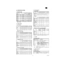
[6] SETTING AND ADJUSTMENTS
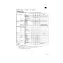
1. List of adjustment items
Section
Adjustment item
Adjustment
procedure
A. Process
(1)
Developing doctor gap
adjustment
adjustment
(2)
MG roller main pole position
adjustment
adjustment
MG roller main
pole position
adjustment
pole position
adjustment
(3)
Developing bias voltage
adjustment
adjustment
SIM8-1/44-15
(4)
Main charger grid voltage
adjustment
adjustment
SIM8-2/44-15
(5)
Transfer charger adjustment
SIM8-6
(6)
Separation charger bias
voltage adjustment
voltage adjustment
SIM8-7
(7)
Photoconductor marking
sensor sensitivity (gain)
adjustment
sensor sensitivity (gain)
adjustment
SIM44-2
Image density sensor
sensitivity (gain) adjustment
SIM44-2
sensitivity (gain) adjustment
SIM44-2
SIM44-2
(8)
Toner concentration
adjustment (auto developer
adjustment)
adjustment (auto developer
adjustment)
SIM25-2
B. Laser scanner
(exposure)
(exposure)
(1)
Horizontal image distortion
adjustment
adjustment
LSU lever
adjustment
adjustment
(2)
Print off-center adjustment
SIM50-10
(3)
Laser power setting (copier
mode)
mode)
SIM61-2/44-15
SIM61-4
Printer mode
SIM61-4
Printer mode
C. Scanner
(1)
Vertical image distortion
balance adjustment
balance adjustment
Copy lamp
unit installing
position
adjustment
unit installing
position
adjustment
(2)
Vertical image distortion
balance adjustment
balance adjustment
No. 2/No. 3
mirror base
installing
position
adjustment
mirror base
installing
position
adjustment
(3)
Vertical (sub scanning
direction) distortion adjustment
[Winding pulley position
adjustment]
direction) distortion adjustment
[Winding pulley position
adjustment]
Winding pulley
position
adjustment
position
adjustment
(4)
Horizontal (main scanning
direction) distorion adjustment
[Lower rail height adjustment]
direction) distorion adjustment
[Lower rail height adjustment]
F rail height
adjustment
adjustment
(5)
Main scanning direction
magnification ratio adjustment
magnification ratio adjustment
CCD unit
position
adjustment
position
adjustment
(6)
Main scanning direction
magnification ratio adjustment
magnification ratio adjustment
SIM48-1
Sub scanning direction
magnification ratio adjustment
magnification ratio adjustment
SIM48-1
*
Including the adjustment with
SPF, RSPF
SPF, RSPF
(7)
Copy image position, image
loss, void area adjustment
loss, void area adjustment
SIM50-1/2
(8)
Original off-center adjustment
SIM50-12
*
Including the adjustment with
SPF
SPF
(9)
Original off-center adjustment
SIM50-12
*
Including the adjustment with
SPF,RADF, RSPF
SPF,RADF, RSPF
Section
Adjustment item
Adjustment
procedure
D. Image density
adjustment
adjustment
(1)
Test chart setting
SIM 46-2/9/10/
11
11
E. Paper feed
(1)
Manual paper feed size
detection level adjustment
detection level adjustment
SIM40-2
(2)
Paper feed off-center
adjustment
adjustment
F. Paper transport
(1)
Separation pawl operation
timing adjustment
timing adjustment
SIM51-1
(2)
Paper resist amount
adjustment
adjustment
SIM51-2
G. Others
(1)
Original size sensor detection
level adjustment
level adjustment
SIM41-2
(2)
Original size sensor detection
level adjustment
level adjustment
SIM41-1
(3)
Waste toner full detection level
adjustment
adjustment
(4)
Touch panel adjustment
SIM65-1
(5)
Key touch sound volume
adjustment
adjustment
Sound volume
adjustment
adjustment
H. SPF
(1)
Hinge height check and
adjustment
adjustment
Table glass
clearance
adjustment
clearance
adjustment
(2)
Open/close sensor position
adjustment
adjustment
SIM 2-02
I. RADF (AR-RF1)
(When the RADF is
installed)
(When the RADF is
installed)
(1)
Document lead edge stop
position adjustment
position adjustment
SIM 53-1
(2)
Resist/timing/paper exit sensor
adjustment
adjustment
SIM 53-2
(3)
Test mode with DIP switch
J. RADF (AR-RF2)
(When the RADF is
installed)
(When the RADF is
installed)
(1)
Document lead edge stop
position adjustment
position adjustment
SIM 53-1
(2)
Resist/timing/paper exit sensor
adjustment
adjustment
SIM 53-2
(3)
Test mode with DIP switch
K. RSPF
Lead edge position adjustment
SIM 50-1/2/6/7
Magnification ratio adjustment
SIM 48-1
No. 1 resist quantity adjustment
SIM 51-2
No. 2 resist quantity adjustment
SIM 51-2
Image loss adjustment
SIM 50-1/2/6/7
Center shift adjustment
50-12
Reflection type sensor
adjustment
adjustment
SIM 53-2
Image distortion adjustment
Distortion
screw
adjustment
screw
adjustment
Back surface resist adjustment
SB resist plate
adjustment
adjustment
Skew adjustment
Upper/lower
guide
adjustment
guide
adjustment
AR-505
8/18/1999
6 – 1
2. Copier adjustment
A. Process section
(1) Developing doctor gap adjustment
1) Remove the screw and the connector which connect the toner
hopper and the developing unit, and separate them.
2) Loosen the DV doctor fixing screw A.
3) Insert a 0.53mm (0.6mm for AR-280/285/335) thickness gauge
into the clearance of 40mm
~
70mm from the DV doctor edge.
4) Press the DV doctor in the arrow direction and tighten the DV
doctor fixing screw. (Perform the same procedure for the front and
the rear frame.)
the rear frame.)
5) Check that the clearance (2 positions) at 40mm
~
70mm from the
both ends is 0.53
±
0.03mm (0.6
±
0.03mm for AR-280/285/335).
*
When inserting a thickness gauge, be careful not to scratch the
DV doctor and the MG roller.
DV doctor and the MG roller.
(2) MG roller main pole position adjustment
1) Remove the screw and the connector which connect the toner
hopper and the developing unit, and separate them. Put the devel-
oping unit on a flat floor.
oping unit on a flat floor.
2) Tie a needle or pin on a string.
3) Hold the string and put the needle horizontally and move it toward
the MG roller. (Do not use a clip which is too big to have a correct
position since the MG roller diameter is small.)
position since the MG roller diameter is small.)
4) With the needle tip at 2
~
3 mm apart from the MG roller surface,
mark the point on the surface which is on the extended line of the
needle tip.
needle tip.
5) Measure the distance between the marking position and surface P
of the developing unit and check that it is 17mm.
If the distance is not as specified above, loosen the fixing screw of
the main pole adjustment plate, and move the adjustment plate to
adjust.
the main pole adjustment plate, and move the adjustment plate to
adjust.
(3) Developing bias voltage adjustment
1) Set the digital multi-meter range to the DCV range.
2) Put the test probes between the DV bias output check pin (CN2-1
pin) of the high voltage unit and the chassis (GND).
30mm
40mm
40mm
30mm
A
17.0mm
2~3mm
P
2~3mm
17.0mm
AR-505
6 – 2
8/18/1999
3) Execute SIM 8-1.
The DV bias can be measured without installing the OPC drum
and the developing unit.
and the developing unit.
4) When the output voltage is within the adjustment range, change
the displayed value and adjust. (1 step: about 1 V)
Adjustment range
AR-501/505
Others
Developing negative bias
voltage (Auto)
voltage (Auto)
–425
±
5V
–500
±
5V
Developing negative bias
voltage (Character)
voltage (Character)
–500
±
5V
–500
±
5V
Developing negative bias
voltage (Character, Photo)
voltage (Character, Photo)
–500
±
5V
–500
±
5V
Developing negative bias
voltage (Photo)
voltage (Photo)
–500
±
5V
–500
±
5V
Developing bias (Printer)
–500
±
5V
–500
±
5V
Developing positive bias voltage
+150
±
5V
+150
±
5V
(The value and the output voltage may not coincide.)
(4) Main charger grid voltage adjustment
1) Install the DV unit, the drum holder unit, and the charger units to
the copier.
2) Turn on the main switch, and execute SIM 8-2 to check the grid
voltage set value.
(Measurement at the high voltage PWB check point)
3) Remove the rear cabinet.
4) Connect the digital multi-meter to the grid voltage output check pin
(CN2-5 pin).
5) Set the digital multi-meter range to the DCV range.
(Use a digital multi-meter which allows measurement up to
DC1000 V.)
DC1000 V.)
6) Manually turn on the door switch.
7) Turn on the main switch, and execute SIM 8-2 to check.
8) If the output voltage is not in the specified range, change the
displayed value and adjust. (1 step: about 1V)
Adjustment range
AR-280/
285/ 335
AR-250/281/
286/336/405
286/336/405
AR-501/505
Grid voltage (Auto)
–642
±
5V
–602
±
5V
–570
±
5V
Grid voltage
(Character)
(Character)
–642
±
5V
–602
±
5V
–645
±
5V
Grid voltage
(Character, Photo)
(Character, Photo)
–642
±
5V
–602
±
5V
–645
±
5V
Grid voltage (Photo)
–642
±
5V
–602
±
5V
–645
±
5V
Grid voltage (Printer)
–642
±
5V
–602
±
5V
–645
±
5V
Grid voltage (FAX)
–642
±
5V
–602
±
5V
–645
±
5V
(The value and the output may not coincide.)
(5) Transfer charger current adjustment
a. Special measurement tool
UKOG-0110FCZZ
UK0G
-0110FCZZ
A
(QCLIZ0005FCZZ)
(QCLIZ0006FCZZ)
(QCLIZ0010FCZZ)
(QCLIZ0004FCZZ)
(QCLIZ0002FCZZ)
PHOG-0007FCZZ
QTIPH0017FCZZ
(VRN-RT2EK304F)
300K
Ω
X 2
Electrode sheet (UKOG-0110FCZZ)
Electrode sheet harness (DHAI-0304FCZZ)
Orange
Orange
Blue
White
Black
White
Red
(Parts arrangement)
Orange
White
Blue
Black
(Microswitch)
(QSW-M0118FCZZ)
Green
Blue
Black
Yellow
Red
AR-505
8/18/1999
6 – 3

