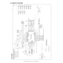
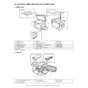
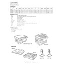
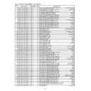
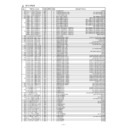
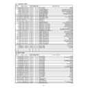
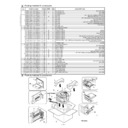
Read Sharp AR-122E (serv.man9) Service Manual online
AR-122E/152E/153E/157E SIMULATION, TROUBLE CODES 10 - 1
[10] SIMULATION, TROUBLE CODES
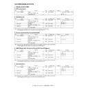
1. Entering the simulation mode
To enter the serviceman simulation mode, press the keys as follows:
Clear
→
Density select
→
Clear
→
Density select
To cancel the simulation mode, press the clear key.
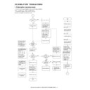
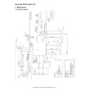
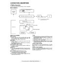
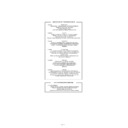
Flow chart of entering the simulation mode
Flow chart of entering the simulation mode
1
YES
NO
NO
YES
YES
YES
1
NO
NO
YES
Is there a sub
code ?
code ?
Press the COPY
key.
key.
Press the COPY key.
The COPY QUANTITY
display blinks to indicate
"00" and the machine
display blinks to indicate
"00" and the machine
enters the ready
state for sub code input.
state for sub code input.
Enter the sub code with
the COPY QUANTITY key.
the COPY QUANTITY key.
10th digit
1st digit:
Press the COPY key.
The current set adjustment
value and the counter
value are displayed on the
COPY QUANTITY
value and the counter
value are displayed on the
COPY QUANTITY
displayed Sensor check,
etc. are displayed by the
etc. are displayed by the
alarm lamps, etc.
To change the current set
values, enter with the COPY
QUANTITY key.
values, enter with the COPY
QUANTITY key.
10th digit:
1st digit:
Count up of values:
COPY QUANTITY key
COPY QUANTITY key
Count down of values:
Zoom key + COPY
QUANTITY key
Zoom key + COPY
QUANTITY key
The entered value
is displayed on the
COPY QUANTITY
display.
is displayed on the
COPY QUANTITY
display.
Press the COPY
key.
key.
The entered value
is registered.
is registered.
Is it the
Perform the operation
according to the
simulation number.
according to the
simulation number.
performed ?
Press the clear key.
All displays on the
operation panel go off,
and the machine enters
the ready state for
entering the main code.
operation panel go off,
and the machine enters
the ready state for
entering the main code.
Press the clear key.
End
Is the
main code the
same ?
main code the
same ?
Is the
sub code
displayed ?
sub code
displayed ?
Press the clear key.
The COPY QUANTITY
display blinks to indicate
the previously set sub
enters the ready 7 state for
sub code input.
display blinks to indicate
the previously set sub
enters the ready 7 state for
sub code input.
code, and the machine
Press the clear key.
Enter the new main
code.
code.
The main code is
displayed on the
COPY QUANTITY
display.
displayed on the
COPY QUANTITY
display.
Start
Press the clear key.
Press the exposure
mode selector key.
mode selector key.
All displays on the
operation panel go off,
and the machine enters
operation panel go off,
and the machine enters
he ready state for entering
he main code.
he main code.
Count up of values:
COPY QUANTITY key
Count down of values:
Zoom key + COPY
QUANTITY key
COPY QUANTITY key
Count down of values:
Zoom key + COPY
QUANTITY key
The main code is
displayed on the
COPY QUANTITY
display.
displayed on the
COPY QUANTITY
display.
simulation for
operation
check?
Is another
simulation to be
Enter the main code with
the COPY QUANTITY key.
the COPY QUANTITY key.
10th digit:
1st digit:
Count up of values:
COPY QUANTITY key
Count down of values:
Zoom key + COPY
QUANTITY key
COPY QUANTITY key
Count down of values:
Zoom key + COPY
QUANTITY key
Press the clear key.
Press the exposure
mode selector key.
mode selector key.
Within 1sec
Within 1sec
Within 1sec
AR-122E/152E/153E/157E SIMULATION, TROUBLE CODES 10 - 2
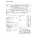
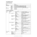
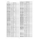
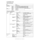
2. List of simulations
Sim
No.
Kind of
main code
Sub
code
Operation
01
Optical system
01
Mirror scan operation
06
Aging of mirror scanning
02
SPF Individual
load operation
load operation
02
SPF sensor status display
03
Motor ON
04
Paper feed solenoid ON
05
Pressure release solenoid ON
(RSPF)
(RSPF)
06
Resist clutch ON (RSPF)
07
Gate solenoid ON (RSPF)
05
Lamp ON
check
check
01
Operation panel display check
02
Fusing lamp, cooling fan operation
check
check
03
Copy lamp ON
06
Machine
individual load
operation
individual load
operation
01
Paper feed solenoid ON
02
Resist solenoid ON
07
Aging
01
Warm-up display and aging with jam
06
Intermittent aging
08
High voltage
output check
output check
01
Developing bias
02
Main charger (Grid high)
03
Grid voltage (Low)
06
Transfer charger
10
Other
None Toner motor aging
14
Trouble reset
None Cancel of troubles other than U2
16
U2 trouble
reset
reset
None Cancel of U2 trouble
20
01
Maintenance counter clear
21
01
Maintenance cycle setup
02
Mini maintenance cycle setup (Valid
only when the destination is set to
Japan AB series.)
only when the destination is set to
Japan AB series.)
22
Counter
display
display
01
Maintenance counter display
02
Maintenance preset value display
04
JAM total counter display
05
Total counter display
06
Developer counter display
08
SPF counter display
12
Drum counter display
14
P-ROM version display
17
Copy counter display
18
Printer counter display
19
Scanner mode counter display
21
Scanner counter display
22
SPF JAM counter display
24
Special
counter clear
counter clear
01
JAM total counter clear
04
SPF counter clear
06
Developer counter clear
07
Drum counter clear
08
Copy counter clear
09
Printer counter clear
13
Scanner counter clear
14
SPF JAM total counter clear
15
Scanner mode counter clear
25
Main motor
ON
ON
01
Main motor operation check (Cooling
fan motor rotation check)
fan motor rotation check)
10
Polygon motor ON
26
Various setup
01
Manual feed setup
02
(R) SPF setup
03
Second cassette setup
04
Machine duplex setup
06
Destination setup
07
Machine conditions check
20
Rear edge void setup
30
CE mark support control ON/OFF
37
Developer life-over termination
cancel
cancel
38
Cancel of stop at drum life over
39
Memory capacity check
40
Polygon motor OFF time setup
(Time required for turning OFF after
completion of printing)
(Time required for turning OFF after
completion of printing)
42
Transfer ON timing control setup
43
Side void setup
44
SPF document rear edge read setup
62
Energy-save mode copy lamp setup
63
Fan control select setup
64
Heater control setup during the
scanner mode
scanner mode
30
Sensor
operation
check
(Standard
provision)
operation
check
(Standard
provision)
01
Paper sensor status display
43
Fusing
temperature
setup
temperature
setup
01
Fusing temperature setup (Normal
copy)
copy)
04
Fusing temperature setup 2
05
Fusing temperature setup in duplex
copy
copy
09
Setup of fusing control of postcard
size paper
size paper
46
Exposure
adjustment
adjustment
01
Copy density adjustment (300dpi)
02
Copy density adjustment (600dpi)
18
Image contrast adjustment (300dpi)
19
γ
table setup or AE operation mode
setup
20
SPF exposure correction
29
Image contrast adjustment (600dpi)
31
Image sharpness adjustment
32
Copier color reproduction setup
48
Magnification
ratio correction
and black level
adjustment
ratio correction
and black level
adjustment
01
Front/rear (main scanning) direction
and scan (sub scanning) direction
magnification ratio adjustment and
black level adjustment
and scan (sub scanning) direction
magnification ratio adjustment and
black level adjustment
49
01
Flash ROM program writing mode
50
Lead edge
adjustment
adjustment
01
Lead edge image position
10
Center offset adjustment
18
Memory reverse position adjustment
in duplex copy
in duplex copy
19
Duplex copy rear edge void
adjustment
adjustment
51
Timing
adjustment
adjustment
02
Resist quantity adjustment
53
08
SPF scan position automatic
adjustment
adjustment
61
Laser system
operation
operation
03
Polygon motor check
(HSYNC output check)
(HSYNC output check)
63
Shading
01
Shading check
64
Self print
01
Self print
Sim
No.
Kind of
main code
Sub
code
Operation
AR-122E/152E/153E/157E SIMULATION, TROUBLE CODES 10 - 3
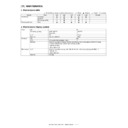
3. Contents of simulations
Input method: Clear key
→
Exposure Select key
→
Clear key
→
Exposure Select key
Main
code
code
Sub
code
Content
01
01
Mirror scan operation
(Operation/Procedure)
1. When this simulation is executed, the mirror home position is detected.
(Operation/Procedure)
1. When this simulation is executed, the mirror home position is detected.
2. When the _START key is pressed, scanning is executed at the speed corresponding to the currently set copy magnification ratio.
The copy magnification ratio can be arbitrarily set with the magnification ratio select key/zoom key.
06
Aging of mirror scanning
When the PRINT switch is pressed, the mirror base performs full scan at the speed of the set magnification ratio. After 3 sec, the mirror
case performs full scan again. These procedures are repeated until the clear key is pressed. (When the PRINT switch is pressed once,
the ready lamp keeps OFF.)
The status of the mirror home position sensor is displayed with the photoconductor cartridge lamp. (The lamp is ON when the mirror is
at the home position.)
During aging, the copy lamp keeps ON.
02
02
SPF sensor status display
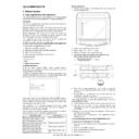
ON/OFF of the sensors in the SPF can be checked with the following lamps.
ON/OFF of the sensors in the SPF can be checked with the following lamps.
03
Motor ON
(Operation/Procedure)
When the start key is pressed, the SPF motor rotates for 10 sec at the speed corresponding to the currently set magnification ratio.
(Operation/Procedure)
When the start key is pressed, the SPF motor rotates for 10 sec at the speed corresponding to the currently set magnification ratio.
04
Paper feed solenoid ON
(Operation/Procedure)
When the start key is pressed, the SPF paper feed solenoid repeats ON (500 ms) and OFF (500 ms) 20 times.
(Operation/Procedure)
When the start key is pressed, the SPF paper feed solenoid repeats ON (500 ms) and OFF (500 ms) 20 times.
05
Pressure release solenoid ON (RSPF)
(Operation/Procedure)
When the start key is pressed, the RSPF document transport solenoid (SPFS) repeats ON (500 ms) and OFF (500 ms) 20 times.
(Operation/Procedure)
When the start key is pressed, the RSPF document transport solenoid (SPFS) repeats ON (500 ms) and OFF (500 ms) 20 times.
06
Resist clutch ON (RSPF)
(Operation/Procedure)
When the start key is pressed, the RSPF resist clutch (SRRC) repeats ON (500 ms) and OFF (500 ms) 20 times.
(Operation/Procedure)
When the start key is pressed, the RSPF resist clutch (SRRC) repeats ON (500 ms) and OFF (500 ms) 20 times.
07
Gate solenoid ON (RSPF)
(Operation/Procedure)
When the start key is pressed, the RSPF gate solenoid (SGS) repeats ON (500 ms) and OFF (500 ms) 20 times.
(Operation/Procedure)
When the start key is pressed, the RSPF gate solenoid (SGS) repeats ON (500 ms) and OFF (500 ms) 20 times.
05
01
Operation panel display check
• When the PRINT switch is pressed, all LEDs (including 7-segment LEDs) on the operation panel are lighted. (LED check mode)
• When the PRINT switch is pressed, all LEDs (including 7-segment LEDs) on the operation panel are lighted. (LED check mode)
• When 1Up key is pressed, the LEDs on the operation panel are lighted individually from the top left to the bottom right in sequence.
After completion of all individual lighting, all LEDs are lighted simultaneously. (The 7-segment LED lights the three-digit sections at
the same time.)
Individual lighting frequency
ON: 300ms,
OFF: 20ms
• When the CLEAR key is pressed, this simulation is terminated.
• When the PRINT switch is pressed in the LED check mode, the machine enters the Key input check mode.
“Key input check mode”
When the machine enters the Key input check mode, the value display section indicates “– – –.” Every time any key on the operat ion
panel is pressed, the entered value is added and displayed on the value display section. However, the keys that were pressed once are
not counted again.
• When the PRINT switch is pressed, the entered value is added and displayed for 3 sec and all the LEDs are lighted. (LED lighting
check mode)
(Note for Key input check mode)
• Press the PRINT switch at the end. (If it is pressed in the middle of the process, the entered value up to that moment is displayed for
• Press the PRINT switch at the end. (If it is pressed in the middle of the process, the entered value up to that moment is displayed for
3 sec and the machine enters the LED lighting check mode. (ALL the LEDs are lighted.))
• Multiple key inputs are ignored.
02
Fusing lamp, cooling fan operation check
When the PRINT switch is pressed, the fusing lamp repeats operations of 500ms-ON and 500ms-OFF 5 times. During that time, the
cooling fan motor rotates.
When the PRINT switch is pressed, the fusing lamp repeats operations of 500ms-ON and 500ms-OFF 5 times. During that time, the
cooling fan motor rotates.
Sensor name
Display lamp
Mirror home position sensor
OPC drum cartridge replacement lamp
Display
Sensor
Developer cartridge replacement lamp
Document set detection (SPID)
Jam lamp
SPF document transport detection (SPPD)
Photoconductor cartridge replacement lamp
SPF cover open/close detection (SDOD)
SPF jam lamp
SPF open/close detection (SDSW)
FAX document size detection
Paper size detection
FAX document size detection
Paper size detection
AR-122E/152E/153E/157E SIMULATION, TROUBLE CODES 10 - 4
05
03
Copy lamp ON
(Operation/Procedure)
When the START key is pressed, the copy lamp is lighted for 5 sec.
(Operation/Procedure)
When the START key is pressed, the copy lamp is lighted for 5 sec.
06
01
Paper feed solenoid ON
(Operation/Procedure)
When the START key is pressed, the paper feed solenoid selected by the tray select key repeats ON (500ms) and OFF (500ms) 20
times.
(Operation/Procedure)
When the START key is pressed, the paper feed solenoid selected by the tray select key repeats ON (500ms) and OFF (500ms) 20
times.
02
Resist solenoid ON
(Operation/Procedure)
When the START key is pressed, the resist solenoid (RRS) repeats ON (500ms) and OFF (500ms) 20 times.
(Operation/Procedure)
When the START key is pressed, the resist solenoid (RRS) repeats ON (500ms) and OFF (500ms) 20 times.
07
01
Warm-up display and aging with jam
(Operation/Procedure)
1. When the simulation is executed, warming up is started.
2. Warm-up time is counted and displayed every second on the copy quantity display.
3. After completion of warm-up, the time count is stopped and the ready lamp is lighted.
4. Press the clear key to clear the warm-up time display, set the copy quantity, and press the START key, and the machine will copy
the set quantity repeatedly.
This simulation is canceled by turning off the power or executing any simulation which performs hardware reset.
06
Intermittent aging
(Operation/Procedure)
1. When the simulation is executed, warming up is started.
2. After completion of warm-up, the ready lamp is lighted.
3. Set the copy quantity and press the START key, and the machine will copy the set quantity repeatedly.
4. After 3 sec of the interval time from completion of copying the set quantity, the machine will resume copying.
5. The above operation 4 is repeated.
This simulation is canceled by turning off the power or executing any simulation which performs hardware reset.
08
01
Developing bias
(Operation/Procedure)
When the START key is pressed, the developing bias is outputted for 30 sec.
(Operation/Procedure)
When the START key is pressed, the developing bias is outputted for 30 sec.
02
Main charger (Grid high)
(Operation/Procedure)
When the START key is pressed, the main charger output is supplied for 30 sec in the grid voltage HIGH mode.
(Operation/Procedure)
When the START key is pressed, the main charger output is supplied for 30 sec in the grid voltage HIGH mode.
03
Grid voltage (Low)
(Operation/Procedure)
When the START key is pressed, the main charger output is supplied for 30 sec in the grid voltage LOW mode.
(Operation/Procedure)
When the START key is pressed, the main charger output is supplied for 30 sec in the grid voltage LOW mode.
06
Transfer charger
(Operation/Procedure)
When the START key is pressed, the transfer charger output is supplied for 30 sec.
(Operation/Procedure)
When the START key is pressed, the transfer charger output is supplied for 30 sec.
10
None Toner motor aging
(Operation/Procedure)
When the START key is pressed, the toner motor output is supplied for 30 sec.
When the START key is pressed, the toner motor output is supplied for 30 sec.
14
None Cancel of troubles other than U2
(Operation/Procedure)
After canceling the trouble, the simulation is also automatically canceled.
After canceling the trouble, the simulation is also automatically canceled.
16
None Cancel of U2 trouble
(Operation/Procedure)
1. When the START key is pressed, the EEPROM total counter check sum is rewritten and the trouble is canceled.
2. After canceling the trouble, the simulation is also automatically canceled.
1. When the START key is pressed, the EEPROM total counter check sum is rewritten and the trouble is canceled.
2. After canceling the trouble, the simulation is also automatically canceled.
20
01
Maintenance counter clear
When the PRINT switch is pressed, the maintenance count is cleared and the value “000000” is displayed.
When the PRINT switch is pressed, the maintenance count is cleared and the value “000000” is displayed.
21
01
Maintenance cycle setup
The currently set code (default) of the maintenance cycle is displayed, and the newly set data are saved.
The currently set code (default) of the maintenance cycle is displayed, and the newly set data are saved.
Main
code
code
Sub
code
Content
Code
Setup
0
3,000 sheets
1
6,000 sheets
2
9,000 sheets
3
13,000 sheets
4
25,000 sheets
*Default
5
Free (999,999 sheets)

