Read Sharp AM-400 (serv.man8) Service Manual online
AM-400DE
2 – 1
AM-400DE
Service Manual
CHAPTER 2.
ADJUSTMENTS
[1] Adjustments
1. General
Since the following adjustments and settings are provided for this
model, make adjustments and/or setup as necessary.
model, make adjustments and/or setup as necessary.
2. Adjustments of output voltage (FACTORY ONLY)
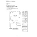
1. Install the power supply unit in the machine.
lines. Confirm that outputs are within the limits below.
2.1. Output voltage settings
CNPUM
CNTCT
CNROLSNS
CNTCVR
CNMM
CNFM
CNBYPE
CNPIN
CNPW
CNLIU
CNLSR
CNPM
CNRTH
CNOUT2
CNOUT1
CNCIS
CNHV
CNSCM
CNPN
CNFRT
CNORG
CNHPS
CNSP
CNUSB
CONTROL PWB
(TOP SIDE)
CNPW
1
14
1
14
Output
Voltage limits
+24VMAIN
23.04V~24.96V
+24VSUB
23.04V~24.96V
Connector
CNPW
Pin No.
CNPW
1
+24VSUB
2
3
4
5
3
4
5
+24VMAIN
6
+24VMAIN
7
DG
8
9
9
10
DG
11
+5VMAIN
12
+3.3VMAIN
+5VMAIN
4.75V~5.25V
MG
MG
MG
MG
DG
/HEATER ON
13
14
/PWRLY
/ZC
/ZC
+3.3VMAIN
3.201V~3.399V
Connector
CN6
Pin No.
1
N.C.
2
3
3
+24VMAIN
+24VS
Connector
CNHT
Pin No.
1
N.C.
2
3
3
N
L
Connector
CN2
Pin No.
1
2
2
1
CN6
1
3
1
2
CN2
CNHT
1
3
INTERLOCK
SWITCH
THERMAL
FUSE-2
FUSING UNIT
POWER SUPPLY
PWB (TOP SIDE)
AM-400DE
2 – 2
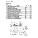
3. High voltage power check
3.1. General
Note: Since the parts of this PWB cannot be supplied, change it as a unit.
CAUTION HIGH VOLTAGE AREA MAX. 4000V
CAUTION
DO NOT TOUCH!
(VR51)
CAUTION - HIGH VOLTAGE
The unit's back cover should never be opened by
anyone other than a qualified serviceperson.
There are many high voltage parts inside the unit,
and touching them is dangerous.
The unit's back cover should never be opened by
anyone other than a qualified serviceperson.
There are many high voltage parts inside the unit,
and touching them is dangerous.
CAUTION HIGH VOLTAGE AREA MAX. 4000V
CAUTION - HIGH VOLTAGE
The unit's back cover should never be opened by
anyone other than a qualified serviceperson.
There are many high voltage parts inside the unit,
and touching them is dangerous.
The unit's back cover should never be opened by
anyone other than a qualified serviceperson.
There are many high voltage parts inside the unit,
and touching them is dangerous.
J22
J21
J21
Q52
D60
D58
D1
D8
D2
D3
D4
C6
D5
D7
D9
C5
CN4
R93
J51
J12
J11
J52
C7
R15
Q3
B1
R1
J5
J6
CN3
C1
VR1
D10
CN1
D61
D53
C9
VR51
D62
J1
J3
J2
B51
C65
C31
VR31
C56
D54
D52
J4
J31
J41
R67
J42
J32
D31
Q38
R16
QJ005
QJ071
C32
R41
R42
R81
R103
R80
R79 R78
D41
D42
Q31
Q32
Q33
Q34
Q36
Q37
Q35
R102
R36
R37
R38
R39
R40
R71
R72
R73
R74
R60
R43
R75
R61
R58
R50
R48
R54
R52
R55
C62
C51
Q58
Q57
C61
R51
R53
R56
R98
R94
R59
R65
R44
R8
R3
R3
R7
R10
R11
C4
R13
R14
R9
C2
R66
R14
R17
R63
R2
R4
R3
R19
R101
R6
R5
C53
C54
C66
C55
C52
C8
IC1
R70
R69
R66
R64
R62
R91
R92
R49
R47
R99
R57
R18
R100
Q51
Q1
CN1
R76
R46
R77
R83
R85
R86
R84
R87
R88 R89 R90
R34
R32 R31
R33 R35
D59
D57 D56 D55
AM-400DE
2 – 3
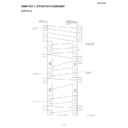
3.2. MC Voltage Check Point
1) MC Voltage
CAUTION - HIGH VOLTAGE
The unit's back cover should never be opened by anyone other than
a qualified serviceperson. There are many high voltage parts inside
the unit, and touching them is dangerous.
The unit's back cover should never be opened by anyone other than
a qualified serviceperson. There are many high voltage parts inside
the unit, and touching them is dangerous.
J22
J21
Q52
D60
D58
D1
D8
D2
D3
D4
C6
D5
D7
D9
C5
CN4
R93
J51
J12
J11
J52
C7
R15
Q3
B1
R1
J5
J6
CN3
C1
VR1
D10
CN1
D61
D53
C9
VR51
D62
J1
J3
J2
B51
C65
C31
VR31
C56
D54
D52
J4
J31
J41
R67
J42
J32
D31
Q38
R16
QJ005
QJ071
GND (-)
MC Voltage Check Point (-)
(There is danger of an electric shock!)
Use Measuring instrument:
Use Measuring instrument:
Input Resistance : more than 100 M
Ω
Maximum Voltage : more than 2 kV
VOLTAGE
MC : - 950 V ± 20 V (PRINTING)
MC : - 850 V ± 20 V (CLEANING)
MC : - 950 V ± 20 V (PRINTING)
MC : - 850 V ± 20 V (CLEANING)
Voltage(v)
300Hz
Time(s)
Type
-570V
-950V
-1330V
-950V
-1330V
Tolerance
± 67V
± 20V
± 67V
± 20V
± 67V
AM-400DE
2 – 4
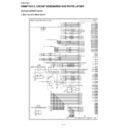
3.3. TC Voltage Check Point
1) TC Voltage
CAUTION - HIGH VOLTAGE
The unit's back cover should never be opened by anyone other than
a qualified serviceperson. There are many high voltage parts inside
the unit, and touching them is dangerous.
The unit's back cover should never be opened by anyone other than
a qualified serviceperson. There are many high voltage parts inside
the unit, and touching them is dangerous.
J22
J21
Q52
D60
D58
D1
D8
D2
D3
D4
C6
D5
D7
D9
C5
CN4
R93
J51
J12
J11
J52
C7
R15
Q3
B1
R1
J5
J6
CN3
C1
VR1
D10
CN1
D61
D53
C9
VR51
D62
J1
J3
J2
B51
C65
C31
VR31
C56
D54
D52
J4
J31
J41
R67
J42
J32
D31
Q38
R16
QJ005
QJ071
GND (-)
TC Voltage Check Point (+)
(There is danger of an electric shock!)
Use High Voltage Tester:
Requirement of Measuring instrument:
Use High Voltage Tester:
Requirement of Measuring instrument:
Input Resistance : more than 100 M
Ω
Maximum Voltage : more than 5 kV
VOLTAGE
TC (+) : + 3600 V ± 72 V (PRINTING)
TC (-) : - 500 V ± 50 V (CLEANING)
TC (+) : + 3600 V ± 72 V (PRINTING)
TC (-) : - 500 V ± 50 V (CLEANING)
Voltage(v)
300Hz
Time(s)
Type
-3980V
-3600V
-3220V
-3600V
-3220V
Tolerance
± 72V

