Read Sharp AL-1611 (serv.man13) Service Manual online
AL-1611/AL-1622
DISASSEMBLY AND ASSEMBLY
11 – 1
[11] DISASSEMBLY AND ASSEMBLY
WARNING:Before performing the disassembly procedure, be sure to
remove the power cord to prevent against an electric shock.
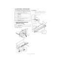
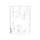
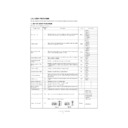
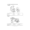
1. HIGH VOLTAGE SECTION/DUPLEX
TRANSPORT SECTION
A. Transfer charger unit
B. Charger wire
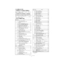
No.
Item
1
High voltage section/Duplex transport section
2
Optical section
3
Fusing section
4
Paper exit section
5
MCU
6
Optical frame unit
7
LSU
8
Tray paper feed section/Paper transport section
9
Manual multi paper feed section
10
Power section
11
SPF section <AL-1622 only>
No.
Content
A
Transfer charger unit
B
Charger wire
( 2 )
( 1 )
( 4 )
( 3 )
( 3 )
( 5 )
( 5 )
Installation: The spring tip must be between two reference ribs.
• The charger wire must be free from twist or bending.
• Be sure to put the charger wire in the V groove.
( 2 )
( 1 )
( 1 )
( 1 )
( 1 )
( 1 )
( 1 )
( 3 )
AL-1611/AL-1622
DISASSEMBLY AND ASSEMBLY
11 – 2
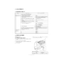
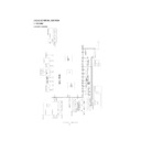
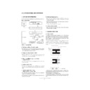
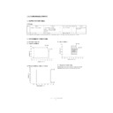
2. OPTICAL SECTION
A. Table glass
B. Copy lamp unit
C. Copy lamp
D. Lens unit
Note: Do not remove screws which are not indicated in the figure. If the
height of the base plate is changed, it cannot be adjusted in the
market.
Lens unit attachment reference
No.
Content
A
Table glass
B
Copy lamp unit
C
Copy lamp
D
Lens unit
Disassembly: Be sure to put No. 2/3 mirror unit to the positioning plate (A).
Assembly:
Put the notched surface of wire holder (3) downward, tighten
temporarily, and install.
Adjustment:
Main scanning direction distortion balance adjustment
( 1 )
( 1 )
( 2 )
( 3 )
( 3 )
( 4 )
( 2 )
( 3 )
( 2 )
( 3 )
( 1 )
( A )
( A )
( 4 )
( 4 )
( 5 )
( 6 )
( 4 )
( 5 )
Attach the lens unit so that the lens unit number on the lens adjust-
ment plate is aligned with the scribe line on the base plate.
Example:Lens unit number -2.8 Attach the lens unit at 2 scales in the
paper exit direction from the reference line.
Note: Never touch the other screws than the unit attachment screw.
The lens unit is supplied only in a whole unit.
( 3 )
( 1 )
( 1 )
( 2 )
AL-1611/AL-1622
DISASSEMBLY AND ASSEMBLY
11 – 3
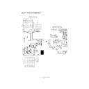
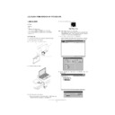
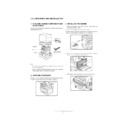
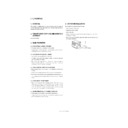
3. FUSING SECTION
A. Fusing unit removal
B. Thermostat
C. Thermistor
D. Heater lamp
Assembly: Insert the spring (A) into the hole (B) in the fusing frame.
No.
Contents
A
Fusing unit
B
Thermostat
C
Thermistor
D
Heater lamp
E
Upper heat roller
F
Separation pawl
G
Lower heat roller
( )
( )
(1)
(1)
( 2 )
( 3 )
( 1 )
( 1 )
Installation: Check that the thermistor is in contact with the upper heat
roller.
Assembly: Put the paper guide earth spring (A) under the paper guide
(B) before fusing.
( 2 )
( 1 )
(A)
(B)
(2)
(1) (2)
AL-1611/AL-1622
DISASSEMBLY AND ASSEMBLY
11 – 4
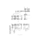
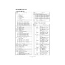
E. Upper heat roller
*
Apply heat-resistive grease (UKOG-0235FCZZ).
F. Separation pawl
Disassembly: There are three pawls on the fusing cover. Remove the
screws and slide the fusing cover to the right to remove.
The heater lamp is fixed on the fusing cover with a
The heater lamp is fixed on the fusing cover with a
screw. Slide the fusing cover to the front and remove the
screw, then remove the heater lamp.
Assembly: Put the fusing harness (A) on the heater lamp (B) as shown
in the figure and fix them together. Place the fusing harness
inside the rib (C).
(3)
(4)
(3)
(B)
(A)
( 6 )
( 5 )
( 8 )
( 9 )
( 7 )
( 8 )
( 1 0 )
( A )
( B )
( C )
( 2 )
( 1 )
(4)
(3)
(3)
∗
∗
(2)
(1)
(2)
(2)
(1)
(1)
(3)
(3)

