Read Sharp PN-E521 (serv.man13) Technical Bulletin online
IDP 2013 08 02
Date of Issue:
9
th
August 2013
Classification:
Yellow
IDP TECHNICAL BULLETIN
Page 1 of 5
Sharp Electronics (UK) Limited
Reference
– PNF-A132
Revision - 1
White
– Carry out as required
Yellow
– Carry out as required and whenever the unit comes in for service
Red
– Carry out on all units
MODELS
PNE521
REASON
The unit will not turn on in low temperatures.
A boot failure has been observed with this model due to the low temperature. (The
backlight is turned on momentarily then turned off. Or not turned on at all.) The
countermeasure for this problem is described below.
Note - it becomes difficult to turn on the backlight under the temperature below 0 °C
due to the characteristic of CCFL (fluorescent lighting backlight). Check the
temperature and lighting time of the backlight on the unit once this boot failure is
reported. It is necessary to evaluate whether the failure reported is due to low
temperature.
ACTION
Insufficient operation margin in the matching of impedance of backlight and inverter
circuit for low temperature environment.
The backlight is turned off or not turned on at all due to the operation of protecting
circuit on inverter circuit.
To increase the operation margin for boot under low temperature environment, the
part on Inverter PWB (RDENC2591TPZF [master PWB]) has been changed so that
maximum inverter output voltage (lamp voltage) allowed to apply is increased.
[R7586A] 1MΩ => 470kΩ (Parts code: VRSRCY2AY474J)
[R7585A] 1MΩ => 470kΩ (Parts code: VRSRCY2AY474J)
This counter measure was implemented from serial number 1******5 (May 2011)
REF NO
DESCRIPTION
PART NUMBER
PRICE CODE
Resistor
VRSRCY2AY474J
AY
IDP 2013 08 02
Date of Issue:
9
th
August 2013
Classification:
Yellow
IDP TECHNICAL BULLETIN
Page 2 of 5
Sharp Electronics (UK) Limited
Reference
– PNF-A132
Revision - 1
White
– Carry out as required
Yellow
– Carry out as required and whenever the unit comes in for service
Red
– Carry out on all units
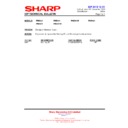
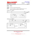
Modification to increase the operation margin for boot under low temperature environment
IDP 2013 08 02
Date of Issue:
9
th
August 2013
Classification:
Yellow
IDP TECHNICAL BULLETIN
Page 3 of 5
Sharp Electronics (UK) Limited
Reference
– PNF-A132
Revision - 1
White
– Carry out as required
Yellow
– Carry out as required and whenever the unit comes in for service
Red
– Carry out on all units
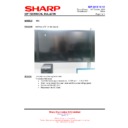
How to identify the countermeasure PWB
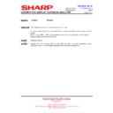
The units with countermeasure Inverter PWB (RDENC2591TPZF [master PWB]) have
the Production Lot number [115--] (which indicates May, 2011 production) or lager.
(Ex. [115--], [116--])
Note - The parts code of modified Inverter PWB does not change.
This countermeasure must be implemented to the units with Inverter PWB with
Production Lot number [114--](which indicates April, 2011 production) or smaller. (Ex.
[113--], [109--], [09Z--])
IDP 2013 08 02
Date of Issue:
9
th
August 2013
Classification:
Yellow
IDP TECHNICAL BULLETIN
Page 4 of 5
Sharp Electronics (UK) Limited
Reference
– PNF-A132
Revision - 1
White
– Carry out as required
Yellow
– Carry out as required and whenever the unit comes in for service
Red
– Carry out on all units
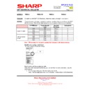
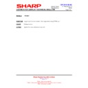
Make sure to put marking on following sections after implementing the
countermeasure:
(1) Inverter PWB
Put a blue dot on lower right of the QR code label on Inverter PWB.
countermeasure:
(1) Inverter PWB
Put a blue dot on lower right of the QR code label on Inverter PWB.
(2) Main unit of PNE521
Put a blue dot on upper right of the label adhered to the back side of main unit.
Put a blue dot on upper right of the label adhered to the back side of main unit.

