Read Sharp LL-T15G3 (serv.man12) Service Manual online
LL-T15G3
APPENDIX : IC DESCRIPTION
6 – 1
■
■
■
■
APPENDIX : IC DESCRIPTION
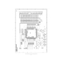
1. PIN DESCRIPTION
1-1. PIN LAYOUT
DOBVSS
BLU_OUTB_7
BLU_OUTB_6
BLU_OUTB_5
BLU_OUTB_4
DOBVDD
BLU_OUTB_3
BLU_OUTB_2
BLU_OUTB_1
BLU_OUTB_0
DOBVSS
RED_OUTA_7
RED_OUTA_6
RED_OUTA_5
RED_OUTA_4
DCVDD
RED_OUTA_3
RED_OUTA_2
RED_OUTA_1
RED_OUTA_0
DCVSS
GRN_OUTA_7
GRN_OUTA_6
GRN_OUTA_5
GRN_OUTA_4
DOBVDD
GRN_OUTA_3
GRN_OUTA_2
GRN_OUTA_1
GRN_OUTA_0
DOBVSS
BLU_OUTA_7
BLU_OUTA_6
BLU_OUTA_5
BLU_OUTA_4
DOBVDD
BLU_OUTA_3
BLU_OUTA_2
BLU_OUTA_1
BLU_OUTA_0
MascotV
120
119
118
117
116
115
114
113
112
111
110
109
108
107
106
105
104
103
102
101
100
119
118
117
116
115
114
113
112
111
110
109
108
107
106
105
104
103
102
101
100
99
98
97
96
95
94
93
92
91
90
89
88
87
86
85
84
83
82
81
98
97
96
95
94
93
92
91
90
89
88
87
86
85
84
83
82
81
1
2
3
4
5
6
7
8
9
2
3
4
5
6
7
8
9
10
11
12
13
14
15
16
17
18
19
20
21
22
23
24
25
26
27
28
29
30
31
32
33
34
35
36
37
38
39
40
11
12
13
14
15
16
17
18
19
20
21
22
23
24
25
26
27
28
29
30
31
32
33
34
35
36
37
38
39
40
41
42
43
44
45
46
47
48
49
50
51
52
53
54
55
56
57
58
59
60
61
62
63
64
65
66
67
68
69
70
71
72
73
74
75
76
77
78
79
80
160
159
158
157
156
155
154
153
152
151
150
149
148
147
146
145
144
143
142
141
140
139
138
137
136
135
134
133
132
131
130
129
128
127
126
125
124
123
122
121
TVCLK
IRQ#
SCS#
SDA
SCL
RST
GPIO1
GPIO0
DCVSS
CONFIG4
CONFIG3
CONFIG2
CONFIG1
CONFIG0
PWM0
PWM1
DCVDD
LCD_VEE
LCD_VDD
LCD_VBL
DCVSS
RED_OUTB_7
RED_OUTB_6
RED_OUTB_5
RED_OUTB_4
DOBVDD
RED_OUTB_3
RED_OUTB_2
RED_OUTB_1
RED_OUTB_0
DOBVSS
GRN_OUTB_7
GRN_OUTB_6
GRN_OUTB_5
GRN_OUTB_4
DOBVDD
GRN_OUTB_3
GRN_OUTB_2
GRN_OUTB_1
GRN_OUTB_0
DIBVDD
CAP_HREF
CAP_HSYNC
CAP_VSYNC
CAP_VSYNC
DIBVSS
BLU_INB_0/Y0
BLU_INB_1/Y1
BLU_INB_2/Y2
BLU_INB_3/Y3
BLU_INB_4/Y4
BLU_INB_5/Y5
BLU_INB_6/Y6
BLU_INB_7/Y7
BLU_INB_1/Y1
BLU_INB_2/Y2
BLU_INB_3/Y3
BLU_INB_4/Y4
BLU_INB_5/Y5
BLU_INB_6/Y6
BLU_INB_7/Y7
DCVDD
GRN_INB_0
GRN_INB_1
GRN_INB_2
GRN_INB_3
GRN_INB_4
GRN_INB_5
GRN_INB_6
GRN_INB_1
GRN_INB_2
GRN_INB_3
GRN_INB_4
GRN_INB_5
GRN_INB_6
GRN_INB_7/RTS0
DCVSS
RED_INB_0/UV0
RED_INB_1/UV1
RED_INB_2/UV2
RED_INB_3/UV3
RED_INB_4/UV4
RED_INB_5/UV5
RED_INB_6/UV6
RED_INB_7/UV7
RED_INB_1/UV1
RED_INB_2/UV2
RED_INB_3/UV3
RED_INB_4/UV4
RED_INB_5/UV5
RED_INB_6/UV6
RED_INB_7/UV7
DIBVDD
DVDD
DVSS
DTEST
VCCD
DGND
VGA_VSYNC
VGA_HSYNC
VGA_HSYNC
SOGI
VCCA
AGND
VREF
CP
CZ
VCCAB
BI
GNDAB
BCLP
VIOP
VBOT
VCCAG
GI
GNDAG
GCLP
TOUTP
TOUIM
VCCAR
RI
RNDAR
RCLP
ADVDD
ADVSS
DCVSS
OSD_FSW
OSD_CLK
OSD_R
OSD_G
OSD_B
OSD_I
DCVDD
RESERVED
XTALO
XTALI
DIBVSS
DISP_DE
DISP_VSYNC
SHCLK
DISP_HSYNC
DCVSS
LL-T15G3
APPENDIX : IC DESCRIPTION
6 – 2
1-2. PIN DESCRIPTION
Pin
No.
Name
Type
Definition
001 DIBVDD
Digital Input Buffer Power
002 CAP_HREF
I
Port B Horizontal Active Qualifier
003 CAP_HSYNC
I
Port B Horizontal Sync Input
004 CAP_VSYNC
I
Port B Vertical Sync Input
005 DIBVSS
Ground Digital Input Buffer Ground
006 BLU_INB_0/Y0
I
Port B Blue Input Bit 0/YUV Data Input
Y0
Y0
007 BLU_INB_1/Y1
I
Port B Blue Input Bit 1/YUV Data Input
Y1
Y1
008 BLU_INB_2/Y2
I
Port B Blue Input Bit 2/YUV Data Input
Y2
Y2
009 BLU_INB_3/Y3
I
Port B Blue Input Bit 3/YUV Data Input
Y3
Y3
010 BLU_INB_4/Y4
I
Port B Blue Input Bit 4/YUV Data Input
Y4
Y4
011 BLU_INB_5/Y5
I
Port B Blue Input Bit 5/YUV Data Input
Y5
Y5
012 BLU_INB_6/Y6
I
Port B Blue Input Bit 6/YUV Data Input
Y6
Y6
013 BLU_INB_7/Y7
I
Port B Blue Input Bit 7/YUV Data Input
Y7
Y7
014 DCVDD
Power Digital Core Power
015 GRN_INB_0
I
Port B Green Input Bit 0
016 GRN_INB_1
I
Port B Green Input Bit 1
017 GRN_INB_2
I
Port B Green Input Bit 2
018 GRN_INB_3
I
Port B Green Input Bit 3
019 GRN_INB_4
I
Port B Green Input Bit 4
020 GRN_INB_5
I
Port B Green Input Bit 5
021 GRN_INB_6
I
Port B Green Input Bit 6
022 GRN_INB_7/
RTS0
I
Port B Green Input Bit 7
023 DCVSS
Ground Digital Core Ground
024 RED_INB_0/
UV0
I
Port B Red Input Bit 0/YUV Data Input
UV0
UV0
025 RED_INB_1/
UV1
I
Port B Red Input Bit 1/YUV Data Input
UV1
UV1
026 RED_INB_2/
UV2
I
Port B Red Input Bit 2/YUV Data Input
UV2
UV2
027 RED_INB_3/
UV3
I
Port B Red Input Bit 3/YUV Data Input
UV3
UV3
028 RED_INB_4/
UV4
I
Port B Red Input Bit 4/YUV Data Input
UV4
UV4
029 RED_INB_5/
UV5
I
Port B Red Input Bit 5/YUV Data Input
UV5
UV5
030 RED_INB_6/
UV6
I
Port B Red Input Bit 6/YUV Data Input
UV6
UV6
031 RED_INB_7/
UV7
I
Port B Red Input Bit 7/YUV Data Input
UV7
UV7
032 DIBVDD
Power Digital Input Buffer Power
033 DVDD
Power Digital VDD
034 DVSS
Ground Digital ground
035 DTEST
O
Digital test output
036 VCCD
Power Digital power
037 DGND
Ground Digital ground
038 VGA_VSYNC
I
Port A vertical SYNC
039 VGA_HSYNC
I
Port A horizontal SYNC
040 SOGI
I
Port A Sync-On-Green input
041 VCCA
Power Analog power for PLL
042 AGND
Ground Analog ground for PLL
043 VREF
I
External 25V reference voltage
044 CP
I
PLL loop filter for pole
045 CZ
I
PLL loop filter for zero
046 VCCAB
Power B channel analog power
047 BI
I
B channel analog input
048 GNDAB
Ground B channel analog ground
049 BCLP
O
B channel internal clamp voltage out-
put
put
050 VTOP
O
ADC resistor ladder top decoupling
capacitor
capacitor
051 VBOT
O
ADC resistor ladder bottom decou-
pling capacitor
pling capacitor
052 VCCAG
Power G channel analog power
053 GI
I
G channel analog input
054 GNDAG
Ground G channel analog ground
055 GCLP
O
G channel internal clamp voltage out-
put
put
056 TOUTP
O
Differential testing output plus
057 TOUTM
O
Differential testing output minus
058 VCCAR
Power R channel analog power
059 RI
I
R channel analog input
060 RNDAR
Ground R channel analog ground
061 RCLP
O
R channel internal clamp voltage out-
put
put
062 ADVDD
(VDD_PLL)
Power Display PLL Analog Power
063 ADVSS
(VSS_PLL)
Ground Display PLL Analog Ground
064 DCVSS
Ground Digital Core Ground
065 OSD_FSW
I
External OSD Window Display Enable
066 OSD_CLK
O
Clock Output For External OSD Con-
troller Chip
troller Chip
067 OSD_R
I
R Data Input From External OSD Con-
troller Chip
troller Chip
068 OSD_G
I
G Data Input From External OSD Con-
troller Chip
troller Chip
069 OSD_B
I
B Data Input From External OSD Con-
troller Chip
troller Chip
070 OSD_I
I
Intensity Input From Ext OSD Control-
ler Chip
ler Chip
071 DCVDD
Power Digital Core Power
072 Reserved
R
Reserved
073 XTAL
O
Crystal Out
074 XTALI
I
Crystal Input
075 DIBVSS
Ground Digital Input Buffer Ground
076 DISP_DE
O
Display Enable
077 DISP_VSYNC
O
Display Vertical Sync
Pin
No.
Name
Type
Definition
LL-T15G3
APPENDIX : IC DESCRIPTION
6 – 3
078 SHCLK
O
Shift Clock
079 DISP_HSYNC
O
Display Horizontal Sync
080 DCVSS
Ground Digital Core Ground
081 BLU_OUTA_0
O
Display Port A Blue Output Bit 0
082 BLU_OUTA_1
O
Display Port A Blue Output Bit 1
083 BLU_OUTA_2
O
Display Port A Blue Output Bit 2
084 BLU_OUTA_3
O
Display Port A Blue Output Bit 3
085 DOBVDD
Power Digital Output Buffer Power
086 BLU_OUTA_4
O
Display Port A Blue Output Bit 4
087 BLU_OUTA_5
O
Display Port A Blue Output Bit 5
088 BLU_OUTA_6
O
Display Port A Blue Output Bit 6
089 BLU_OUTA_7
O
Display Port A Blue Output Bit 7
090 DOBVSS
Ground Digital Output Buffer Ground
091 GRN_OUTA_0
O
Display Port A Green Output Bit 0
092 GRN_OUTA_1
O
Display Port A Green Output Bit 1
093 GRN_OUTA_2
O
Display Port A Green Output Bit 2
094 GRN_OUTA_3
O
Display Port A Green Output Bit 3
095 DOBVDD
Power Digital Output Buffer Power
096 GRN_OUTA_4
O
Display Port A Green Output Bit 4
097 GRN_OUTA_5
O
Display Port A Green Output Bit 5
098 GRN_OUTA_6
O
Display Port A Green Output Bit 6
099 GRN_OUTA_7
O
Display Port A Green Output Bit 7
100 DCVSS
Ground Digital Core Ground
101 RED_OUTA_0
O
Display Port A Red Output Bit 0
102 RED_OUTA_1
O
Display Port A Red Output Bit 1
103 RED_OUTA_2
O
Display Port A Red Output Bit 2
104 RED_OUTA_3
O
Display Port A Red Output Bit 3
105 DCVDD
Power Digital Core Power
106 RED_OUTA_4
O
Display Port A Red Output Bit 4
107 RED_OUTA_5
O
Display Port A Red Output Bit 5
108 RED_OUTA_6
O
Display Port A Red Output Bit 6
109 RED_OUTA_7
O
Display Port A Red Output Bit 7
110 DOBVSS
Power Digital Output Buffer Ground
111 BLU_OUTB_0
O
Display Port B Blue Output Bit 0
112 BLU_OUTB_1
O
Display Port B Blue Output Bit 1
113 BLU_OUTB_2
O
Display Port B Blue Output Bit 2
114 BLU_OUTB_3
O
Display Port B Blue Output Bit 3
115 DOBVDD
Power Digital Output Buffer Power
116 BLU_OUTB_4
O
Display Port B Blue Output Bit 4
117 BLU_OUTB_5
O
Display Port B Blue Output Bit 5
118 BLU_OUTB_6
O
Display Port B Blue Output Bit 6
119 BLU_OUTB_7
O
Display Port B Blue Output Bit 7
120 DOBVSS
Ground Digital Output Buffer Ground
121 GRN_OUTB_0
O
Display Port B Green Output Bit 0
122 GRN_OUTB_1
O
Display Port B Green Output Bit 1
123 GRN_OUTB_2
O
Display Port B Green Output Bit 2
124 GRN_OUTB_3
O
Display Port B Green Output Bit 3
125 DOBVDD
Power Digital Output Buffer Power
126 GRN_OUTB_4
O
Display Port B Green Output Bit 4
Pin
No.
Name
Type
Definition
127 GRN_OUTB_5
O
Display Port B Green Output Bit 5
128 GRN_OUTB_6
O
Display Port B Green Output Bit 6
129 GRN_OUTB_7
O
Display Port B Green Output Bit 7
130 DOBVSS
Ground Digital Output Buffer Ground
131 RED_OUTB_0
O
Display Port B Red Output Bit 0
132 RED_OUTB_1
O
Display Port B Red Output Bit 1
133 RED_OUTB_2
O
Display Port B Red Output Bit 2
134 RED_OUTB_3
O
Display Port B Red Output Bit 3
135 DOBVDD
Power Digital Output Buffer Power
136 RED_OUTB_4
O
Display Port B Red Output Bit 4
137 RED_OUTB_5
O
Display Port B Red Output Bit 5
138 RED_OUTB_6
O
Display Port B Red Output Bit 6
139 RED_OUTB_7
O
Display Port B Red Output Bit 7
140 DCVSS
Ground Digital Core Ground
141 LCD_VBL
O
LCD Panel VBL Backlight Control
142 LCD_VDD
O
LCD Panel VDD Source Control
143 LCD_VEE
O
LCD Panel VEE Control
144 DCVDD
Power Digital Core Power
145 PWM1
146 PWM0
147 CONFIG0
I
Configuration Pin 0 (I2C Slave Address
Bit 0)
Bit 0)
148 CONFIG1
I
Configuration Pin 1 (I2C Slave Address
Bit 1)
Bit 1)
149 CONFIG2
I
Configuration Pin 2 (I2C Slave Address
Bit 2)
Bit 2)
150 CONFIG3
I
Configuration Pin 3 (I2C Slave Address
Bit 3)
Bit 3)
151 CONFIG4
I
Configuration Pin 3 (Serial Bus Select)
152 DCVSS
Ground Digital Core Ground
153 GPI00
I/O
General Purpose Input/Output
154 GPI01
I/O
General Purpose Input/Output
155 RST
I
System Reset
156 SCL
I/O
Host Interface Serial Clock
157 SDA
I/O
Host Interface Serial Data
158 SCS#
I
Serial Chip Select
159 IRQ#
O
Interrupt To Host
160 TVCLK
I
Port B Clock Input
Pin
No.
Name
Type
Definition


