Read Sharp LL-T1501A (serv.man8) Service Manual online
DOWNSTRAEM
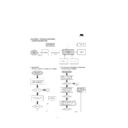
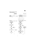
LCD UNIT
LANP
15 inch LCD
LANP
INVERTER
1
LCD SIGNAL INPUT
2
3
4
6
RGB, H/V
INPUT
POWER UNIT
AC SW
[AC INPUT]
DOWNSTRAEM
UPSTRAEM
5
KEY-SWITCH UNIT
AUTO BRIGHTNESSS UNIT
INTERFACE
UNIT
7
ONLY 1511A
AC ADAPTER
USB HUB UNIT
DC POWER
[FROM PC]
[FROM PC]
[TO USB DEVICE]
STAND UNIT
DISPLAY UNIT
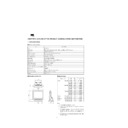
CHAPTER 5. BLOOK DIAGRAM
Unit terminals
LCD SIGNAL INPUT
Used connector : FX8-60P-SV (HIROSE)
Pin No.
Symbol
Function
1
GND
GND
2
RB0
RED Even pixel data signal
(LSB)
3
RB1
RED
4
RB2
RED
5
RB3
RED
6
RB4
RED
7
RB5
RED
(MSB)
8
GND
GND
9
GB0
GREEN Even pixel data signal
(LSB)
10
GB1
GREEN
11
GB2
GREEN
12
GB3
GREEN
13
GB4
GREEN
14
GB5
GREEN
(MSB)
15
GND
GND
16
BB0
BLUE Even pixel data signal
(LSB)
17
BB1
BLUE
18
BB2
BLUE
19
BB3
BLUE
20
BB4
BLUE
21
BB5
BLUE
(MSB)
22
GND
GND
23
RA0
RED Odd pixel data signal
(LSB)
24
RA1
RED
25
RA2
RED
26
RA3
RED
27
RA4
RED
28
RA5
RED
(MSB)
29
GND
GND
30
GA0
GREEN Odd pixel data signal
(LSB)
31
GA1
GREEN
32
GA2
GREEN
33
GA3
GREEN
34
GA4
GREEN
35
GA5
GREEN
(MSB)
36
GND
GND
37
BA0
BLUE Odd pixel data signal
(LSB)
38
BA1
BLUE
39
BA2
BLUE
40
BA3
BLUE
41
BA4
BLUE
42
BA5
BLUE
(MSB)
43
GND
GND
44
REV1
(GND)
45
GND
GND
46
V
sync
Vertical synchronizing signal
47
H
sync
Horizontal synchronizing signal
48
DE
Data enable signal (Display position signal)
49
GND
GND
50
GND
GND
51
CKB
Sampling clock
52
CKA
Sampling clock
53
GND
GND
54
GND
GND
55
GND
GND
(GND)
56
MODE
Timing signal select
57
Vcc
+5V power supply
58
Vcc
+5V power supply
59
Vcc
+5V power supply
60
Vcc
+5V power supply
JP6 (To Inverter Terminal)
Used connector : PH_6
Pin No.
Symbol
Function
1
ON / OFF
HIGH = ON, LOW = OFF +5V
2
GND
GND
3
BRIGHT
Brightness control of inverter +5V
4
GND
GND
5
+12V
+12V IN
6
+12V
+12V IN
JP4 (To Key Switch Board Terminal)
Used connector : PH_9P
Pin No.
Symbol
Function
1
KEY MENU
MENU
2
KEY SELECT
SELECT
3
KEY UP
UP
4
KEY DOWN
DOWN
5
HOT KEY
HOT KEY
6
SOFT PWA
SOFT POWER
7
LED AMBEA
LED ORANGE
8
LED GREEN
LED GREEN
9
GND
GND
J2 (Power Supply Input Terminal) FROM STAND
Used connector : CON 4P
Pin No.
Symbol
Function
1
+12V
+12V supply from power BD
2
+12V
+12V supply from power BD
3
GND
GND
4
GND
GND
JP3 (Power Supply Input Terminal From AC ADAPTER)
Used connector : POWER_JACK20_B
Pin No.
Symbol
Function
1
GND
2
+12V
+12V supply from AC ADAPTER
3
GND
J1(Signal Input Terminal)
Used connector : PH12P
Pin No.
Symbol
Function
1
SCL
DDC
2
SDA
DDC
3
DDC +5V
DDC
4
V-SYNC-
V-SYNC
5
H-SYNC
H-SYNC
6
GND
GND
7
RED
RED
8
GND
GND
9
GREEN
GREEN
10
GND
GND
11
BLUE
BLUE
12
GND
GND
JP8 (From BRIGHT SENSER) (Only 15UA)
Used connector : PH_4P
Pin No.
Symbol
Function
1
+5V
+5V
2
GND
GND
3
AUTO BRI CTRL
Auto Bright Control
4
GND
GND
Display


