Read Sharp LL-T1500A (serv.man15) Service Manual online
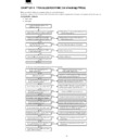
(4) <Screen error>
Is the signal output of the 25th pin of
the U10 at low level (0 V)?
the U10 at low level (0 V)?
No
Check the microprocessor control circuit for
the U10.
the U10.
Yes
It the 8th pin of the U18 at DC+5V?
Check the DC+5 V power supply line (% Vb)
and power supply circuit for the U18.
and power supply circuit for the U18.
Is the signal output of the 1st pin of
the U12 at high level (Cd+5 V)?
the U12 at high level (Cd+5 V)?
Check the power supply control circuit for
the U12.
the U12.
Is the 2nd pin of the U14 at CD+3.3 V?
Check the DC+3.3 V power supply line (3.3 Vb)
and the power supply circuit for the U14.
and the power supply circuit for the U14.
Does the entire screen of the LCD
remain white?
remain white?
Check the LCD connector and LCD module.
Check the LCD control signal
circuit for the U1 and U3.
circuit for the U1 and U3.
Does the entire screen of the LCD
remain black?
remain black?
Check the LCD control signal circuit for
the U1 and U3.
the U1 and U3.
Is the size of the LCD screen abnormal?
Are the adjustment items, ADJUSTMENT,
MODE, and SELECT, properly set?
MODE, and SELECT, properly set?
Check the LCD control signal circuit for
the U1 and U3.
the U1 and U3.
Adjust and set the adjustment
items properly, following the
screen adjustment procedure.
items properly, following the
screen adjustment procedure.
Check the PLL circuits for the
U2, U4, U5, U6, U10, and U11.
U2, U4, U5, U6, U10, and U11.
Does the LCD screen jolt or flicker?
Are the adjustment items ADJUSTMENT,
MODE, and SELECT set properly?
MODE, and SELECT set properly?
Check the PLL circuits for the U2,
U4, U5, U6, U10, and U11.
U4, U5, U6, U10, and U11.
Adjust and set the adjustment
items properly, following the
screen adjustment procedure.
items properly, following the
screen adjustment procedure.
Do the colors of the LCD screen
abnormal?
abnormal?
Are the adjustment items GAIN, CONTROL,
and WHITE BALANCE properly set?
and WHITE BALANCE properly set?
Is the digital color signal output of the U2
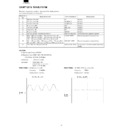
normal? (See Waveform diagram 9.)
normal? (See Waveform diagram 9.)
Is the digital color signal input and output of
the U1 normal? (See Waveform 10.)
the U1 normal? (See Waveform 10.)
Check the LCD connector and LCD module.
Adjust or set the adjustment
items, following the screen
adjustment procedure.
items, following the screen
adjustment procedure.
Check the video amplifier
circuit for the U7.
circuit for the U7.
Check the AD conversion
circuit for the U2.
circuit for the U2.
Check the color signal
processing circuit for the U1
and U3.
processing circuit for the U1
and U3.
Is the OSD display of the LCD screen
abnormal?
abnormal?
Check the color signal processing circuit for
the U1 and U3.
the U1 and U3.
Check the OSD display circuit
for the U8, U10, and U11.
for the U8, U10, and U11.
Is the LCD screen normal at the time of
composite sync or sync-on green?
composite sync or sync-on green?
Check the synchronizing signal processing
circuit for the U7, U19, U21, U22 and U23.
circuit for the U7, U19, U21, U22 and U23.
Check the memory circuit for the U10 and u11.
The LCD unit is normal.
No
No
No
No
No
No
No
No
Yes
Yes
Yes
Yes
No
No
No
Yes
Yes
Yes
No
No
No
No
No
Yes
Yes
No
No
No
Yes
Yes
No
Are the signal outputs of the 9th and 14th pins
of the JP4(See Waveform diagrams 4 and 5.)
of the JP4(See Waveform diagrams 4 and 5.)
Are the output signals of the 15th pin of the U5
and the 8th pin of the U2 normal?
(See Waveform diagrams 6 and 7.)
and the 8th pin of the U2 normal?
(See Waveform diagrams 6 and 7.)
Are the analog color signal outputs of the 29th
pin, 32nd pin, and 35th pin of the U properly
set? (See Waveform diagram 8.)
pin, 32nd pin, and 35th pin of the U properly
set? (See Waveform diagram 8.)
Are the signal outputs of the 13th pin, 14th pin
and 15th pin of the U8 normal?
(See Waveform diagram 11.)
and 15th pin of the U8 normal?
(See Waveform diagram 11.)


