Read Sharp LL-H1513 (serv.man18) Parts Guide online
q
PARTS GUIDE
CONTENTS
Parts marked with "
!
" are important for maintaining the safety of the set. be sure to replace these parts with specified
ones for maintaining the safety and performance of the set.
SHARP CORPORATION
CODE :00ZLLH1513EPE
LCD MONITOR
MODEL
LL-H1513E
1
Mechanism etc.
2
Packing case & Accessories
3
Main PWB unit
4
Key PWB unit
5
Sound PWB unit
■
index
– 1 –
1
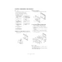
Mechanism etc.
NO.
PARTS CODE
PRICE
RANK
NEW
MARK
PART
RANK
DESCRIPTION
1
G C A B C 1 0 1 8 M P Z Z
AS
N
D
Display mask
2
C P W B N 1 0 3 4 M P 0 1
AP
N
E
Key PWB unit
3
Q C N W - 1 0 6 0 M P Z Z
AD
N
C
Key cable
4
J K N B Z 1 0 1 3 M P Z Z
AD
N
C
Key button
5
P F I L W 1 0 0 8 M P Z Z
AC
N
D
LED filter
6
L A N G T 1 0 6 7 M P Z Z
AD
N
C
Key switch angle
7
L X - B Z 1 0 0 9 M P Z Z
AA
N
C
Screw(2
×
4)
8
P G S K - 1 0 0 4 D C Z Z
AF
C
Gasket
9
P G S K - 2 0 2 8 H C Z Z
AF
C
Gasket
10
R C O R F 1 0 1 1 M P Z Z
AK
C
Core
11
P S H E Z 1 0 4 7 M P Z Z
AD
N
C
Fixing tape
12
V V L Q 1 5 0 X 1 D Z 8 A
CX
N
B
LCD(15 ASV)
13
P Z E T L 1 0 0 9 M P Z Z
AF
N
C
Inverter insulating sheet
14
L A N G T 1 0 6 8 M P Z Z
AG
N
C
LCD angle L
16
L X - B Z 1 0 0 7 M P Z Z
AA
C
Screw(M3X6)
17
R U N T Z 1 0 1 5 M P Z Z
BF
N
B
Inverter unit
18
Q C N W - 1 0 5 8 M P Z Z
AG
N
C
Inverter cable
19
X B P S D 2 0 P 0 3 0 0 0
AA
C
Screw(2
×
3)
20
P S H E Z 1 0 3 4 M P Z Z
AC
N
C
Sheet
21
Q C N W - 1 0 5 5 M P Z Z
AF
N
C
LCD cable A
22
Q C N W - 1 0 5 6 M P Z Z
AG
N
C
LCD cable B
23
L A N G T 1 0 6 9 M P Z Z
AY
N
C
Base angle
24
X B B S D 3 0 P 0 4 0 0 0
AA
C
Screw(3
×
4)
25
X U B S D 3 0 P 0 8 0 0 0
AA
C
Screw(3
×
8)
26
C P W B X 1 0 3 3 M P 0 6
BY
N
E
Main PWB unit
27
X B B S E 3 0 P 0 6 0 0 0
AA
C
Screw(3
×
6)
28
L A N G T 1 0 7 0 M P Z Z
AN
N
C
Connector angle
29
C P W B N 1 0 3 5 M P 0 2
BA
N
E
Sound PWB unit
30
L X - B Z 1 0 1 1 M P Z Z
AC
N
C
Screw
31
P Z E T L 1 0 0 8 M P Z Z
AF
N
C
Power supply insulating sheet
!
32
R D E N T 1 0 0 2 M P Z Z
BE
N
E
Power supply unit
33
Q C N W - 1 0 5 9 M P Z Z
AF
N
C
Sound cable
34
Q C N W - 1 0 5 7 M P Z Z
AG
N
C
Power supply cable
35
P S L D C 1 0 2 4 M P Z Z
AY
N
C
Shield plate
36
P Z E T L 1 0 1 0 M P Z Z
AF
N
C
PS insulating sheet upper
37
G C O V A 1 0 4 0 M P Z Z
AD
N
D
Power supply switch cover
38
G C O V A 1 0 4 1 M P Z Z
AC
N
D
HH jack cover
39
G C A B D 1 0 1 9 M P Z Z
AW
N
D
Display cover
40
P G S K - 1 0 0 3 D C Z Z
AG
C
Gasket
41
X B B S E 3 0 P 0 6 0 0 0
AA
C
Screw(3
×
6)
42
T L A B Z 1 1 3 0 M P Z Z
AD
N
D
Caution label
43
T L A B Z 1 1 5 2 M P Z Z
AD
N
D
I/F label
45
G C O V A 1 0 4 9 M P Z Z
AD
N
D
Tilt cover B
46
G C O V A 1 0 4 8 M P Z Z
AD
N
D
Tilt cover A
47
M H N G - 1 0 0 9 M P Z Z
BN
N
C
Tilt unit
48
G C O V A 1 0 4 5 M P Z Z
AH
N
D
Slide arm F
49
L A N G T 1 0 7 3 M P Z Z
AN
N
C
Slide arm angle
50
L H L D Z 1 0 0 4 M P Z Z
AE
N
C
Tension holder
51
J K N B Z 1 0 1 4 M P Z Z
AE
N
C
Tension knob
52
G C O V A 1 0 4 6 M P Z Z
AG
N
D
Slide arm B
53
M S P R P 1 0 0 5 M P Z Z
AH
N
C
Knob spring
54
G C O V A 1 0 4 7 M P Z Z
AF
N
D
Upper cover
55
G C O V A 1 0 4 2 M P Z Z
AG
N
D
Base arm F
56
L A N G T 1 0 7 2 M P Z Z
AQ
N
C
Base arm angle
57
M S P R P 1 0 0 4 M P Z Z
AR
N
C
Flat spring
58
L A N G T 1 0 7 1 M P Z Z
AG
N
C
Vesa angle
59
G C O V A 1 0 4 4 M P Z Z
AF
N
D
Cable cover
60
P G I D M 1 0 0 2 M P Z Z
AF
C
Slide guide
61
L A N G T 1 0 7 4 M P Z Z
AF
N
C
Install angle
62
G S T N - 1 0 0 8 M P Z Z
AL
N
D
Stand cover
63
L P L T M 1 0 1 9 M P Z Z
AW
N
C
Stand base plate B
64
L P L T M 1 0 1 8 M P Z Z
AX
N
C
Stand base plate A
65
G L E G G 1 0 0 4 M P Z Z
AD
D
Rubber foot
66
X B B S D 3 0 P 0 6 0 0 0
AA
C
Screw(3
×
6)
67
X U B S D 3 0 P 0 8 0 0 0
AA
C
Screw(3
×
8)
68
X U S S D 3 0 P 0 8 0 0 0
AA
C
Screw(3
×
8)
69
X B P S D 3 0 P 0 8 K 0 0
AA
C
Screw(3
×
8K)
70
L X - B Z 1 1 1 1 A C Z Z
AB
N
C
Screw(3
×
3)
71
G C O V A 1 0 4 3 M P Z Z
AG
N
D
Base arm B
72
X B B S E 4 0 P 0 8 0 0 0
AA
C
Screw(4
×
8)
73
X W V S D 3 0 - 0 4 0 0 0
AA
C
Washer
74
T L A B Z 1 1 2 6 M P Z Z
AE
D
No overhaul label
75
T L A B N 1 2 1 9 M P Z Z
AC
D
No. label
76
P G S K - 1 0 0 7 M P Z Z
AE
C
Gasket
77
P S P A Z 1 0 0 7 M P Z Z
AC
N
C
Spacer
78
P S P A Z 1 0 0 8 M P Z Z
AC
N
C
Spacer
79
T L A B M 1 2 2 6 M P Z Z
AG
N
D
Name plate label
– 2 –
1
Mechanism etc.
A
A
B
B
C
C
D
E
E
D
1
4
3
5
2
6
78
78
7
7
7
12
13
8
17
20
16
16
77
16
14
19
19
23
76
76
76
25
18
33
27
27
28
27
24
24
24
24
24
24
27
27
27
26
30
36
27
27
29
32
25 25
24
24
21
22
10
11
9
77
8
16
77
77
35
38
37
40
58
39
41
41
72
72
41
41
43
79
75
42
41
31
34
45
46
67
67
66
69
69
69
62
63
64
68
68 65
65
TP000131
68
68
69
65
65
65
47
48
49
66
50
51
53
55
56
69
73
73
69
69
66
66
66
61
60
59
71
74
54
57
70
52
– 3 –
2
Packing case & Accessories
3
Main PWB unit
NO.
PARTS CODE
PRICE
RANK
NEW
MARK
PART
RANK
DESCRIPTION
1
S P A K A 1 0 8 8 M P Z Z
AV
N
D
Packing add upper
2
S P A K A 1 0 8 9 M P Z Z
AV
N
D
Packing add bottom
3
S P A K G 1 0 9 0 M P Z Z
AU
N
D
Packing case
4
P N N O - 1 0 0 1 M P Z Z
AL
N
D
Screen cleaner cloth
NO.
PARTS CODE
PRICE
RANK
NEW
MARK
PART
RANK
DESCRIPTION
1
Q C N C M 1 0 2 1 M P 0 G
AE
C
Connector(S7B-PH-SM3)
[CN10]
2
Q C N C M 7 0 1 4 S C 0 E
AB
C
Connector(5pin)
[CN5]
3
Q C N C M 7 0 1 4 S C 0 H
AB
C
Connector(8pin)
[CN16]
4
Q C N C W 1 0 4 0 M P Z Z
AF
C
Connector(FH12-36S-0.5SH)
[CN9]
5
Q C N C W 1 0 4 1 M P Z Z
AG
C
Connector(FH12-40S-0.5SH)
[CN11]
6
Q C N C W 1 0 4 2 M P Z Z
AE
C
Connector(FH12-9S-0.5SH)
[CN7]
7
Q S O C N 1 0 1 3 M P Z Z
AG
N
C
Socket(UBA 614-4AMS1BN)
[CN3]
8
Q S O C N 1 0 1 2 M P Z Z
AH
N
C
Socket(USB 622-4AMS1BN)
[CN4]
9
Q J A K J 1 0 0 8 M P Z Z
AF
C
Jack(HSJ2000-01-01C)
[CN8]
10
Q S O C N 1 0 1 0 M P Z Z
AP
C
Socket(DVI-I)(440-29FRDS5WN)
[CN1]
11
Q S O C N 1 0 1 1 M P Z Z
AH
C
Socket(R.G.B)(DV11201-R3)
[CN2]
12
R C - C Z 1 0 6 1 R C 1 A
AF
C
Capacitor(10WV 10
µ
F)
[C28,C34,C36,C4,C6]
R C - C Z 1 0 6 1 R C 1 A
AF
C
Capacitor(10WV 10
µ
F)
[C61,C8]
13
R C I L Z 1 0 0 8 M P Z Z
AH
C
Coil(CDRH127-220)
[L3]
14
R C I L Z 2 4 1 8 R C Z Z
AH
C
Coil(100
µ
H(CDRH127))
[L2]
15
R C - K Z 1 0 5 1 R C 1 A
AC
C
Capacitor(10WV 1.0
µ
F)
[C119,C127,C14,C140,C16]
R C - K Z 1 0 5 1 R C 1 A
AC
C
Capacitor(10WV 1.0
µ
F)
[C20,C27,C33,C58,C80]
16
R C - K Z 2 2 5 1 R C 1 A
AD
C
Capacitor(10WV 2.2
µ
F)
[C100,C105,C65,C68,C72]
R C - K Z 2 2 5 1 R C 1 A
AD
C
Capacitor(10WV 2.2
µ
F)
[C92,C99]
17
R C O R F 1 0 0 9 M P Z Z
AC
C
Core(BK2125HS102)
[R23,R24,R25,R59,R60]
R C O R F 1 0 0 9 M P Z Z
AC
C
Core(BK2125HS102)
[R61,R62,R63]
18
R C O R F 1 0 1 0 M P Z Z
AC
N
C
Core(BK2125LL560)
[FB16,R84]
19
R C O R F 1 0 4 7 L C Z Z
AC
C
Core(FBM2125 330)
[FB12,FB18,FB19,FB20,FB22]
R C O R F 1 0 4 7 L C Z Z
AC
C
Core(FBM2125 330)
[FB23,FB24,FB25,FB26,FB27]
R C O R F 1 0 4 7 L C Z Z
AC
C
Core(FBM2125 330)
[FB28,FB29,FB30]
20
R C O R F 1 0 5 0 L C Z Z
AD
C
Core(FBM4516 111)
[FB32,FB33]
21
R C O R F 2 0 2 4 H C Z Z
AE
C
Core(AC3216M4-300)
[FL1,FL10,FL11,FL12,FL2]
R C O R F 2 0 2 4 H C Z Z
AE
C
Core(AC3216M4-300)
[FL3,FL4,FL5,FL6,FL7]
R C O R F 2 0 2 4 H C Z Z
AE
C
Core(AC3216M4-300)
[FL8,FL9]
22
R C R S C 1 0 0 1 M P Z Z
AK
B
Crystal(4MHz)
[X2]
23
R C R S C 1 1 0 1 A C Z Z
AH
N
B
Crystal(SX-7L 14.318MHz)
[X1]
24
R F I L N 1 0 0 5 M P Z Z
AC
C
Filter(ACB2012M-600)
[FB17,FB21]
25
R F I L N 1 0 1 1 M P Z Z
AG
N
C
Filter(KFN21100)
[FL13]
26
R H - I X 2 8 0 0 A F Z Z
AK
B
8M Flash(HN58X2416TSR)
[IC19]
27
R M P T W 2 1 0 4 Q C J J
AA
B
Block resistor(100K
Ω×
2)
[BR4,BR5]
28
R M P T W 2 1 5 0 Q C J J
AA
B
Block resistor(15
Ω×
2)
[BR2]
29
R M P T W 4 1 0 1 Q C J J
AB
B
Block resistor(100
Ω×
4)
[BR10,BR39,BR40,BR6,BR7]
R M P T W 4 1 0 1 Q C J J
AB
B
Block resistor(100
Ω×
4)
[BR8,BR9]
30
R M P T W 4 1 0 3 Q C J J
AB
B
Block resistor(10K
Ω×
4)
[BR11,BR12,BR37,BR38]
31
R M P T W 4 1 5 0 Q C J J
AA
B
Block resistor(15
Ω×
4)
[BR3]
32
R M P T W 4 1 5 1 Q C J J
AA
N
B
Block resistor(150
Ω×
4)
[BR13,BR14]
33
R M P T W 4 1 5 3 Q C J J
AA
B
Block resistor(15k
Ω×
4)
[BR1]
34
R M P T W 4 2 2 1 Q C J J
AA
N
B
Block resistor(220
Ω×
4)
[BR17,BR18,BR19,BR20,BR21]
R M P T W 4 2 2 1 Q C J J
AA
N
B
Block resistor(220
Ω×
4)
[BR22,BR23,BR24,BR25,BR26]
R M P T W 4 2 2 1 Q C J J
AA
N
B
Block resistor(220
Ω×
4)
[BR27,BR28]
35
V C A A P F 1 C J 8 2 6 M
AH
N
C
Capacitor(16WV 82
µ
F)
[C141,C150]
36
V C C C C Y 1 H H 1 2 0 J
AA
C
Capacitor(50WV 12pF)
[C83,C85]
37
V C C C C Y 1 H H 2 0 0 J
AA
C
Capacitor(50WV 20pF)
[C38,C39]
38
V C C C C Y 1 H H 2 2 0 J
AA
C
Capacitor(50WV 22pF)
[C15,C26,C32]
39
V C C C C Y 1 H H 3 9 0 J
AA
C
Capacitor(50WV 39pF)
[C1,C2,C62,C63]
40
V C E A P H 1 V C 3 3 5 M
AC
C
Capacitor(35WV 3.3
µ
F)
[C23]
41
V C E A P S 1 A C 3 3 6 M
AC
C
Capacitor(10WV 33
µ
F)
[C82,C86]
42
V C E A S D 1 C N 1 0 7 M
AC
C
Capacitor(16WV 100
µ
F)
[C11,C12,C133,C138]
43
V C E A S D 1 C N 3 3 6 M
AC
C
Capacitor(16WV 33
µ
F)
[C104,C120,C79,C87]
44
V C E A S D 1 C N 4 7 6 M
AC
C
Capacitor(16WV 47
µ
F)
[C3]
45
V C E A S D 1 C N 4 7 7 M
AE
C
Capacitor(16WV 470
µ
F)
[C114,C116,C124,C128]
46
V C E A S D 1 E N 1 0 7 M
AD
C
Capacitor(25WV 100
µ
F)
[C117,C155,C157]
47
V C E A S D 1 E N 2 2 7 M
AD
C
Capacitor(25WV 220
µ
F)
[C151,C154]
48
V C E A S D 1 E N 4 7 5 M
AC
C
Capacitor(25WV 4.7
µ
F)
[C40,C41]
49
V C E A S D 1 E N 4 7 6 M
AC
C
Capacitor(25WV 47
µ
F)
[C145]
50
V C E A S D 1 E N 4 7 7 M
AE
C
Capacitor(25WV 470
µ
F)
[C137]
51
V C K Y C Y 1 A R 3 3 4 K
AC
C
Capacitor(10WV 0.33
µ
F)
[C42,C43]
52
V C K Y C Y 1 C B 4 7 3 K
AB
C
Capacitor(16WV 0.047
µ
F)
[C149]
53
V C K Y C Y 1 C F 1 0 4 Z
AA
C
Capacitor(16WV 0.1
µ
F)
[C10,C101,C102,C103,C106]
V C K Y C Y 1 C F 1 0 4 Z
AA
C
Capacitor(16WV 0.1
µ
F)
[C107,C108,C109,C110,C113]
V C K Y C Y 1 C F 1 0 4 Z
AA
C
Capacitor(16WV 0.1
µ
F)
[C115,C121,C122,C125,C126]
V C K Y C Y 1 C F 1 0 4 Z
AA
C
Capacitor(16WV 0.1
µ
F)
[C13,C131,C132,C139,C147]
V C K Y C Y 1 C F 1 0 4 Z
AA
C
Capacitor(16WV 0.1
µ
F)
[C148,C156,C162,C163,C17]

