Read Sharp R-90GCK (serv.man5) Service Manual online
4
R-90GCK
OPERATION
DESCRIPTION OF OPERATING SEQUENCE
The following is a description of component functions
during oven operation.
during oven operation.
OFF CONDITION
Closing the door activates the door sensing switch and
secondary interlock switch and 3rd. latch switch. (In this
condition, the monitor switch contacts are opened.)
secondary interlock switch and 3rd. latch switch. (In this
condition, the monitor switch contacts are opened.)
IMPORTANT:
When the oven door is closed, the contacts COM-NC
of the monitor switch must be open. When the
microwave oven is plugged in a wall outlet (230 - 240V
/ 50Hz), the line voltage is supplied to the noise filter.
When the oven door is closed, the contacts COM-NC
of the monitor switch must be open. When the
microwave oven is plugged in a wall outlet (230 - 240V
/ 50Hz), the line voltage is supplied to the noise filter.
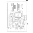
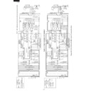
Figure O-1 on page 32
1. The display will show "PRESS STOP".
To set any program or set the clock, you must first touch
the STOP/CLEAR pad. The display will clear, and
" . 0 " will appear.
the STOP/CLEAR pad. The display will clear, and
" . 0 " will appear.
NOTE: When the door is opened, the oven lamp comes
on.
2. A signal is input to the control unit, energizing the coil
of shut-off relay (RY-4). RY4 contacts close, completing
a circuit to the damper motor. The damper motor now
operates moving the damper to the open position,
thereby closing the contacts of the damper switch
inputs a signal to the control unit. The coil of relay RY-
4 is de-energized, opening its contacts, thereby turning
off the damper motor.
a circuit to the damper motor. The damper motor now
operates moving the damper to the open position,
thereby closing the contacts of the damper switch
inputs a signal to the control unit. The coil of relay RY-
4 is de-energized, opening its contacts, thereby turning
off the damper motor.
MICROWAVE COOKING CONDITION
HIGH COOKING
Program desired cooking time by touching the TIME keys.
When the START pad is touched, the following operations
occur:
Program desired cooking time by touching the TIME keys.
When the START pad is touched, the following operations
occur:
1. The contacts of relays are closed and components
connected to the relays are turned on as follows.
(For details, refer to Figure O-2)
(For details, refer to Figure O-2)
RELAY
CONNECTED COMPONENTS
RY-1
Oven lamp/Turntable motor
RY-2
High voltage transformer
RY-3
Convection motor
RY-4
Damper motor
RY-5
Fan motor
RY-6
Convection motor
2. The line voltage is supplied to the primary winding of
the high voltage transformer. The voltage is converted
to about 3.3 volts A.C. output on the filament winding
and high voltage of approximately 2000 volts A.C. on
the secondary winding.
to about 3.3 volts A.C. output on the filament winding
and high voltage of approximately 2000 volts A.C. on
the secondary winding.
3. The filament winding voltage (3.3 volts) heats the
magnetron filament and the high voltage (2000 volts) is
sent to the voltage doubling circuit, where it is doubled
to negative voltage of approximately 4000 volts D.C..
sent to the voltage doubling circuit, where it is doubled
to negative voltage of approximately 4000 volts D.C..
4. The 2450 MHz microwave energy produced in the
magnetron generates a wavelength of 12.24 cm. This
energy is channelled through the waveguide (transport
channel) into the oven cavity, where the food is placed
to be cooked.
energy is channelled through the waveguide (transport
channel) into the oven cavity, where the food is placed
to be cooked.
5. When the cooking time is up, a signal tone is heard and
the relays RY1 + RY2 + RY5 go back to their home
position. The circuits to the oven lamp, high voltage
transformer, fan motor and turntable motor are cut off.
position. The circuits to the oven lamp, high voltage
transformer, fan motor and turntable motor are cut off.
6. When the oven door is opened during a cooking cycle,
the switches come to the following condition.
Switch
Contact
Condition
During
During
Oven Door
Cooking
Open(No cooking)
Secondary interlock
switch
switch
COM-NO
Closed
Opened
Door sensing switch
COM-NO
Closed
Opened
3rd. latch switch
COM-NO
Closed
Opened
Monitor Switch
COM-NC
Opened
Closed
The circuit to the high voltage transformer is cut off
when the contacts of relay RY2, and the contacts
(COM-NO) of the secondary interlock switch are made
open. The circuit to the fan motor is cut off when the
relay RY5 is made open. The circuit to the turntable
motor is cut off when the contacts (COM-NO) of the
secondary interlock switch are made open. The oven
lamp remains on even if the oven door is opened after
the cooking cycle has been interrupted, because the
relay RY1 stays closed. Shown in the display is
remaining time.
7. MONITOR SWITCH CIRCUIT
The monitor switch is mechanically controlled by the
oven door, and monitors the operation of the secondary
interlock switch and the relay RY2.
oven door, and monitors the operation of the secondary
interlock switch and the relay RY2.
7-1. When the oven door is opened during or after the
cycle of a cooking program, the secondary interlock
switch and the door sensing switch must open their
contacts (COM-NO) first. After that the contacts
(COM-NC) of the monitor switch can be closed and
the contacts (COM-NO) of 3rd. latch switch are made
open.
switch and the door sensing switch must open their
contacts (COM-NO) first. After that the contacts
(COM-NC) of the monitor switch can be closed and
the contacts (COM-NO) of 3rd. latch switch are made
open.
7-2. When the oven door is closed, the contacts (COM-
NC) of the monitor switch must be opened and the
contacts (COM-NO) of 3rd. latch switch must be
closed. After that the contacts (COM-NO) of the
secondary interlock switch and the door sensing
switch are made closed.
contacts (COM-NO) of 3rd. latch switch must be
closed. After that the contacts (COM-NO) of the
secondary interlock switch and the door sensing
switch are made closed.
7-3. When the oven door is opened and the contacts
(COM-NO) of the secondary interlock switch remain
closed, the fuse F10A will blow. Because the relay
RY2 and monitor switch are closed and a short circuit
is caused.
closed, the fuse F10A will blow. Because the relay
RY2 and monitor switch are closed and a short circuit
is caused.
MEDIUM HIGH, MEDIUM, MEDIUM LOW, LOW
COOKING
COOKING
When the microwave oven is preset for variable cooking
power, the line voltage is supplied to the high voltage
transformer intermittently within a 32-second time base
through the relay contact which is coupled with the cur-
rent-limiting relay RY2. The following levels of microwave
power are given.
power, the line voltage is supplied to the high voltage
transformer intermittently within a 32-second time base
through the relay contact which is coupled with the cur-
rent-limiting relay RY2. The following levels of microwave
power are given.
5
R-90GCK
NOTE: The ON/OFF time ratio does not correspond
with the percentage of microwave power,
because approx. 3 seconds are needed for
heating of the magnetron filament.
because approx. 3 seconds are needed for
heating of the magnetron filament.
CONVECTION COOKING CONDITION
PREHEATING CONDITION
Program desired convection temperature by touching the
CONV.(˚C) key. When the START key is touched, the
following operations occur: (Figure O-3)
1. The coil of shut-off relays (RY1, RY3 and RY5) are
Program desired convection temperature by touching the
CONV.(˚C) key. When the START key is touched, the
following operations occur: (Figure O-3)
1. The coil of shut-off relays (RY1, RY3 and RY5) are
energized, the oven lamp, cooling fan motor, turntable
motor and convection motor are turned on. The contacts
(COM-NO) of relay RY6 are opened.
motor and convection motor are turned on. The contacts
(COM-NO) of relay RY6 are opened.
2. The coil of relay (RY4) is energized by the control unit.
The damper is moved to the closed position, closing
the damper switch contacts. The closing of the damper
switch contacts sends a signal to the LSI on the control
unit de-energizing the relay (RY4) and opening the
circuit to the damper motor.
the damper switch contacts. The closing of the damper
switch contacts sends a signal to the LSI on the control
unit de-energizing the relay (RY4) and opening the
circuit to the damper motor.
3. The solid-state relays are energized by the control unit
and the main supply voltage is applied to the top and
side heating elements.
side heating elements.
4. When the oven temperature reaches the selected
preheat temperature, the following operations occur:
4-1. The solid-state relays are de-energized by the
4-1. The solid-state relays are de-energized by the
control unit temperature circuit and thermistor,
opening the circuit to the heating elements.
opening the circuit to the heating elements.
4-2. The oven will continue to function for 30 minutes,
turning the heating elements on and off, as needed
to maintain the selected preheat temperature. The
oven will shutdown completely after 30 minutes
to maintain the selected preheat temperature. The
oven will shutdown completely after 30 minutes
CONVECTION COOKING CONDITION
Enter the cooking time by touching TIME keys and select
the temperature by touching CONV.(˚C) key. When the
START pad is touched, the following operations occur:
the temperature by touching CONV.(˚C) key. When the
START pad is touched, the following operations occur:
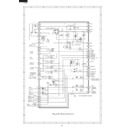
Figure O-3 on page 33
1. The numbers on the digital read-out start to count down
to zero.
2. The oven lamp, turntable motor, cooling fan motor and
convection motor are energized. The contacts (COM-
NO) of relay RY6 are opened.
NO) of relay RY6 are opened.
3. The damper is moved to the closed position.
4. The solid-state relays are energized (if the cavity
4. The solid-state relays are energized (if the cavity
temperature is lower than the selected temperature)
and the main supply voltage is applied to the heating
elements to return to the selected cooking temperature.
and the main supply voltage is applied to the heating
elements to return to the selected cooking temperature.
5. Upon completion of the cooking time, the audible signal
will sound, and oven lamp, turntable motor, cooling fan
motor and convection motor are de-energized. At the
end of the convection cycle, if the cavity air temperature
is above 111˚C, the circuit to RY5 will be maintained (by
the thermistor circuit) to continue operation of the cooling
motor and convection motor are de-energized. At the
end of the convection cycle, if the cavity air temperature
is above 111˚C, the circuit to RY5 will be maintained (by
the thermistor circuit) to continue operation of the cooling
fan motor until the temperature drops below 90˚C, at
which time the relay will be de-energized, turning off the
fan motor. Relay RY3 will however, open as soon as the
convection cycle has ended, turning off the convection
fan motor.
which time the relay will be de-energized, turning off the
fan motor. Relay RY3 will however, open as soon as the
convection cycle has ended, turning off the convection
fan motor.
6. At the end of the convection cook cycle, if the cavity air
temperature is below 120˚C, shut-off relay (RY4) is
energized turning on the damper motor. The damper is
returned to the open position, closing the damper
switch contacts which send a signal to the control unit,
de-energizing shut-off relay (RY4).
energized turning on the damper motor. The damper is
returned to the open position, closing the damper
switch contacts which send a signal to the control unit,
de-energizing shut-off relay (RY4).
GRILL COOKING
Enter cooking tim nd then touch the GRILL key. When the
start pad is touched, following operations occur;
start pad is touched, following operations occur;
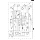
Figure O-4 on page 33
1. The contacts of the relays RY1, RY3 and RY5 are
closed, and the oven lamp, turntable motor, convection
motor and fan motors are energized. The contacts
(COM-NO) of relay RY6 are closed.
motor and fan motors are energized. The contacts
(COM-NO) of relay RY6 are closed.
NOTE :The rotate direction of the convection motor is
reverse to one of the convection cooking by
the relay RY6.
the relay RY6.
2. The damper is moved to the closed position.
3. The solid-state relays are energized and the main
3. The solid-state relays are energized and the main
supply voltage is applied to the top and side heating
elements.
elements.
NOTE :After cooking, the operation of the fan motors,
damper motor is the same as one of the
convection cooking.
convection cooking.
DUAL1 COOKING
Enter cooking time and then touch DUAL1 key. When the
start pad is touched, following operations occur;
start pad is touched, following operations occur;
Figure O-5 on page 34
1. The contacts of the relays RY1, RY3 and RY5 are
closed, and the oven lamp, turntable motor, convection
motor and fan motors are energized. The contacts
(COM-NO) of relay RY6 are closed.
motor and fan motors are energized. The contacts
(COM-NO) of relay RY6 are closed.
NOTE :The rotate direction of the convection motor is
revers to one of the convection cooking.
2. The damper is moved to the closed position.
3. The solid-state relays are energized and the main
3. The solid-state relays are energized and the main
supply voltage is applied to the top and side heating
elements.
elements.
4. The relay RY2 is energized and the microwave energy
is generated by magnetron.
NOTE: After cooking, the operation of the fan motors,
damper motor is the same as one of the
convection cooking.
convection cooking.
DUAL2 COOKING
Enter cooking time and then touch DUAL2 key. When the
start pad is touched, following operations occur;
start pad is touched, following operations occur;
Figure O-6 on page 34
1. The contacts of the relays RY1, RY3 and RY5 are
closed, and the oven lamp, turntable motor, convection
motor and fan motors are energized. The contacts
(COM-NO) of relay RY6 are opened.
motor and fan motors are energized. The contacts
(COM-NO) of relay RY6 are opened.
2. The damper is moved to the closed position.
3. The solid-state relays and relay RY2 are energized,
3. The solid-state relays and relay RY2 are energized,
and the main supply voltage is applied to the top and
side heating elements and the high voltage transformer
alternately.
side heating elements and the high voltage transformer
alternately.
NOTE: After cooking, the operation of the fan motors,
damper motor is the same as one of the
convection cooking.
convection cooking.
100% (HIGH)
32 sec. ON
70% (MEDIUM
HIGH)
Approx. 70%
100%
24 sec. ON
8 sec. OFF
14 sec. OFF
20 sec. OFF
26 sec. OFF
50% (MEDIUM)
Approx. 50%
18 sec. ON
30% (MEDIUM
LOW)
Approx. 30%
12 sec. ON
10% (LOW)
Approx. 10%
6 sec. ON
6
R-90GCK
AUTOMATIC COOKING
Automatic cooking will automatically compute the oven
temperature, microwave power and cooking time. And
the oven will cook according to the special cooking
sequence.
temperature, microwave power and cooking time. And
the oven will cook according to the special cooking
sequence.
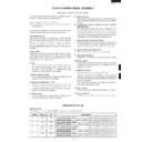
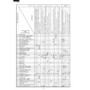
POWER CONTROL FOR MANUAL COOKING
Following table shows the power control for manual
cooking.
cooking.
FIRE SENSING FEATURE (MICROWAVE MODE)
This model incorporates a sensing feature which will stop
the oven's operation if there is a fire in the oven cavity
during microwave cooking. This fire sensing feature will
operate when the microwave power level is set to 80% or
more. This is accomplished by the LSI repeatedly meas-
uring the voltage across the temperature measurement
circuit (thermistor) during it's 32-seconds time base com-
paring the obtained voltage measurements. If the most
recent voltage measured is 300 mV greater than the
previous voltage measured, the LSI judges it as a fire in the
oven cavity and switches off the relays to the power
transformer, fan motor and convection motor. The LSI also
stops counting down and closes the damper door so that
no fresh air will enter the oven cavity. Please refer to the
following section for a more detailed description.
Operation
Please refer to the timing diagrams below.
1. The fire sensing will start after 30 minutes when the
Please refer to the timing diagrams below.
1. The fire sensing will start after 30 minutes when the
oven is started.
2. The thermistor operates within a 32-seconds time base
and it is energized for three (3) seconds and off for 29
seconds. Two (2) seconds after the thermistor is
energized, the voltage across the temperature
measurement circuit is sampled by the LSI and twenty
five (25) seconds after the thermistor is cut off the LSI
turns on the convection fan for three (3) seconds.
seconds. Two (2) seconds after the thermistor is
energized, the voltage across the temperature
measurement circuit is sampled by the LSI and twenty
five (25) seconds after the thermistor is cut off the LSI
turns on the convection fan for three (3) seconds.
3. The above procedure is repeated. If the difference
between the first voltage measured (in step 1) and the
voltage measured when the procedure is repeated
(step 2) is greater than 300 mV the LSI makes the
judgment that there is a fire in the oven cavity and will
switch off the relays to the power transformer, fan
motor and convection motor.
voltage measured when the procedure is repeated
(step 2) is greater than 300 mV the LSI makes the
judgment that there is a fire in the oven cavity and will
switch off the relays to the power transformer, fan
motor and convection motor.
Micro ON
Side heaer
%
-
-
-
70
50
30
10
70
50
30
10
70
50
30
10
70
50
30
10
50
30
10
70
50
30
10
70
50
30
10
70
50
30
10
0
0
0
0
0
0
0
-
-
-
-
-
-
-
-
-
-
-
-
-
-
-
-
-
-
-
-
-
-
-
-
-
-
220
o
C
220
o
C
200
o
C
220 - 250
o
C
180 - 190
o
C
40 - 160
o
C
200
o
C
220 - 250
o
C
180 - 190
o
C
40 - 160
o
C
Side heaer
%
-
100
30
50
70
90
30
50
70
90
30
50
70
90
30
50
70
90
20
20
20
20
50
70
90
30
50
70
90
30
50
70
90
30
50
70
90
20
20
20
20
100
60
60
60
50
50
50
50
40
40
40
40
30
60
60
50
50
50
50
40
40
40
40
30
Top heaer
%
-
100
30
50
70
90
30
50
70
70
30
50
70
70
30
30
10
10
10
10
10
10
50
70
90
30
50
70
70
30
50
70
70
30
30
10
10
10
10
10
10
100
60
50
50
50
50
40
40
40
40
30
30
30
50
50
50
50
40
40
40
40
30
30
30
70%
-
50%
50%
30%
10%
50%
50%
30%
10%
50%
50%
30%
10%
50%
50%
30%
10%
50%
30%
10%
50%
50%
30%
10%
50%
50%
30%
10%
50%
50%
30%
10%
-
-
-
-
-
-
-
-
-
-
-
-
-
-
-
-
-
-
-
-
-
-
-
-
-
Micro
%
10-100
-
70
50
30
10
70
50
30
10
70
50
30
10
70
50
30
10
70
50
30
10
50
30
10
70
50
30
10
70
50
30
10
70
50
30
10
70
50
30
10
-
-
-
-
-
-
-
-
-
-
-
-
-
-
-
-
-
-
-
-
-
-
-
-
-
Micro. OFF
Oven
temperature
Powr down
time
Power after powr down time
Manual
MENU
MICROWAVE
GRILL
GRILL
REHAET
CONV.
(Normal)
(Normal)
DUAL1
DUAL2
Air
Balancel
Jet
Jet
Conv.
Conv.
Conv.
Conv.
Conv.
Conv.
Conv.
Conv. or Jet
-
-
-
-
-
50%
-
-
-
-
-
40 - 250
o
C
250
o
C
230
o
C
200 - 220
o
C
40 -190
o
C
250
o
C
230
o
C
200 - 220
o
C
40 - 190
o
C
250
o
C
230
o
C
200 - 220
o
C
40 - 190
o
C
40 min.
60 min.
60 min.
All
30 min.
All
30 min.
All
45 min.
All
45 min.
None
30 min.
30 min.
20 min.
20 min.
30 min.
30 min.
20 min.
20 min.
60 min.
60 min.
30 min.
20 min.
30 min.
20 min.
20 min.
30 min.
30 min.
20 min.
20 min.
60 min.
60 min.
30 min.
20 min.
-
-
-
-
-
-
-
-
-
-
-
-
-
-
-
-
-
-
-
-
-
-
-
-
-
50%
30%
30%
30%
-
-
30%
30%
30%
20%
30%
30%
30%
20%
30%
30%
30%
20%
30%
30%
20%
30%
30%
30%
20%
30%
30%
30%
20%
-
-
-
20%
20%
20%
-
-
30%
30%
30%
20%
30%
30%
30%
20%
30%
30%
30%
20%
30%
30%
20%
30%
30%
30%
20%
30%
30%
30%
20%
Top heaer Side heaer
Side heaer
Micro.
Micro. ON
Micro. OFF
Cool oven
(Oven Temperature
less than 59˚C)
(Oven Temperature
less than 59˚C)
After preheating
(Oven Temperature
more than 100˚C)
(Oven Temperature
more than 100˚C)
Warm oven
(Oven Temperature
60˚C - 99˚C)
(Oven Temperature
60˚C - 99˚C)
7
R-90GCK
CONVECTION
MOTOR
THERMISTOR
Sensing
Voltage
ON
OFF
ON
OFF
ON
OFF
0 2 3
28
31
32 (sec.)
64 (sec.)
3 sec.
Sensing the voltage across temperature measurement circuit.
3 sec.
The LSI also stops counting down and closes the
damper door so that no fresh air will enter the oven
cavity.
damper door so that no fresh air will enter the oven
cavity.
4. Once the fire sensor feature has shut the unit down, the
programmed cooking cycle may be resumed by
pressing the "START" pad or the unit may be reset by
pressing the "CLEAR" pad.
pressing the "START" pad or the unit may be reset by
pressing the "CLEAR" pad.
FUNCTION OF IMPORTANT COMPONENTS
DOOR OPEN MECHANISM
The door is opened by pulling the door handle down and
forward, referring to the figure D-1. When the door handle
is pulled down, the latch heads are moved upward. And
then when the door handle is pulled forward, the latch
heads are released from the latch hooks right and left.
Now, the door will open.
forward, referring to the figure D-1. When the door handle
is pulled down, the latch heads are moved upward. And
then when the door handle is pulled forward, the latch
heads are released from the latch hooks right and left.
Now, the door will open.
Figure D-1. Door Open Mechanism
DOOR SENSING SWITCH, SECONDARY INTER-
LOCK SWITCH AND 3RD. LATCH SWITCH
LOCK SWITCH AND 3RD. LATCH SWITCH
1. When the oven door is closed, the contacts (COM-NO)
must be closed.
2. When the oven door is opened, the contacts (COM-
NO) must be opened.
MONITOR SWITCH
1. When the oven door is closed, the contacts (COM-NC)
must be opened.
2. When the oven door is opened, the contacts (COM-
NC) must be closed.
3. If the oven door is opened and the contacts (COM-NO)
of the secondary interlock switch and the relay RY2 fail
to open, the fuse F10A blows simultaneously with
closing the contacts (COM-NC) of the monitor switch .
to open, the fuse F10A blows simultaneously with
closing the contacts (COM-NC) of the monitor switch .
CAUTION: BEFORE REPLACING A FUSE TEST THE
SECONDARY INTERLOCK SWITCH, RELAY
RY2 AND MONITOR SWITCH FOR PROPER
OPERATION. (REFER TO CHAPTER "TEST
PROCEDURE".)
RY2 AND MONITOR SWITCH FOR PROPER
OPERATION. (REFER TO CHAPTER "TEST
PROCEDURE".)
FUSE F10A
1. The fuse F10A blows when the contacts (COM-NO) of
the secondary interlock switch and relay RY2 remain
closed with the oven door open and when the monitor
switch closes.
closed with the oven door open and when the monitor
switch closes.
2. If the wire harness or electrical components are short-
circuited, the fuse F10A blows to prevent an electric
shock of fire hazard.
shock of fire hazard.
HIGH VOLTAGE FUSE
The high voltage fuse blows when the high voltage rectifier
or the magnetron is shorted.
or the magnetron is shorted.
NOISE FILTER
The noise filter prevents the radio frequency interference
that might flow back in the power circuit.
that might flow back in the power circuit.
THERMISTOR
The thermistor is a negative temperature coefficient type.
The temperature in the oven cavity is detected through the
resistance of the thermistor, and then the control unit causes
the heater relay to operate, thus the current to the heating
elements is turned ON/OFF. If the convection cooking or
some cooking modes which use the top / side heating
elements is started and the oven temperature does not rise
above 37.8˚C, the control unit will stop the oven after 10
minutes. In this case, the thermistor may be opened.
Monitor switch
Latch hook left
Latch
head
head
3rd. latch
switch
switch
Latch hook right
Latch
head
head
Door handle
Secondary
interlock switch
(Monitored latch switch)
interlock switch
(Monitored latch switch)
Door
sensing switch
(Primary interlock
relay control switch)
sensing switch
(Primary interlock
relay control switch)

