Read Sharp R-795M (serv.man6) Service Manual online
R-795M-
5
1
11
10
2
3
4
6
5
7
10
7
8
9
12
13
14
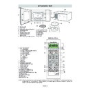
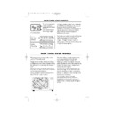
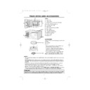
APPEARANCE VIEW
1. Control panel
2. Oven lamp
3. Grill heating element (Top Grill)
4. Waveguide cover
5. Oven cavity
6. Turntable motor shaft
7. Grill heating element
2. Oven lamp
3. Grill heating element (Top Grill)
4. Waveguide cover
5. Oven cavity
6. Turntable motor shaft
7. Grill heating element
(Bottom Grill)
8. Door seals and sealing surfaces
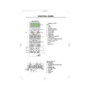
CONTROL PANEL
OVEN
9. Door opening handle
10.Ventilation openings
11.Power cord
12.Outer cabinet
13.Turntable
14.Low rack
10.Ventilation openings
11.Power cord
12.Outer cabinet
13.Turntable
14.Low rack
1. DIGITAL DISPLAY
1-1. LESS/MORE
1-2. MICROWAVE POWER LEVEL
1-3. WEIGHT/PIECES
1-4. MICROWAVE
1-5. BOTTOM GRILL
1-6. TOP GRILL
1-7. COOK
1-8. DEFROST
1-9. AUTO
1-2. MICROWAVE POWER LEVEL
1-3. WEIGHT/PIECES
1-4. MICROWAVE
1-5. BOTTOM GRILL
1-6. TOP GRILL
1-7. COOK
1-8. DEFROST
1-9. AUTO
2. TIME key
3. PIZZA key
4. EXPRESS COOK keys
5. EXPRESS DEFROST keys
6. AUTO COOK key
7. DUAL GRILL key
8. OVEN (
3. PIZZA key
4. EXPRESS COOK keys
5. EXPRESS DEFROST keys
6. AUTO COOK key
7. DUAL GRILL key
8. OVEN (
˚
C) key
9. LESS/MORE keys
10.START/AUTO MINUTE key
11.STOP/CLEAR key
12.KITCHEN TIMER/CLOCK SET key
13.WEIGHT keys
14.POWER LEVEL key
15.GRILL key
16.BREAKFAST key
10.START/AUTO MINUTE key
11.STOP/CLEAR key
12.KITCHEN TIMER/CLOCK SET key
13.WEIGHT keys
14.POWER LEVEL key
15.GRILL key
16.BREAKFAST key
NOTE: If the clock has been set, some one-touch cooking features such as "AUTO MINUTE" are disabled after three
minutes when the oven is not used. These features are automatically enabled when the door is opened and
closed or the STOP/CLEAR key is pressed.
closed or the STOP/CLEAR key is pressed.
COOK
KG PCS
%
AUTO
DEFROST
1-7
1-8
1-9
1-6
1-1
1-2
1-3
1-2
1-3
1-5
1-4
1-4
16
15
14
12
13
1
2
3
4
5
6
8
9
10
10
11
7
R-795M
-
6
OPERATION SEQUENCE
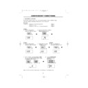
OFF CONDITION
Closing the door activates the monitored latch switch and
the stop switch.
IMPORTANT:
When the oven door is closed, the contacts COM-NC
of the monitor switch must be open. When the micro-
wave oven is plugged in a wall outlet (230 - 240V /
50Hz), the line voltage is supplied to the noise filter.
the stop switch.
IMPORTANT:
When the oven door is closed, the contacts COM-NC
of the monitor switch must be open. When the micro-
wave oven is plugged in a wall outlet (230 - 240V /
50Hz), the line voltage is supplied to the noise filter.
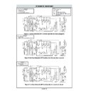
Figure O-1 on page
30
1. The control unit is not energized. The display shows
nothing (Fig. O-1 (a)).
2. Open the door. The contacts (COM-NC) of the moni-
tored latch switch are closed and the control unit is
energized. Then contacts of relays RY1 and RY5 are
closed, and the oven lamp will light and the display will
show "ENERGY SAVE MODE TO CANCEL ENERGY
SAVE MODE SET THE CLOCK" (Fig. O-1(b)).
energized. Then contacts of relays RY1 and RY5 are
closed, and the oven lamp will light and the display will
show "ENERGY SAVE MODE TO CANCEL ENERGY
SAVE MODE SET THE CLOCK" (Fig. O-1(b)).
3. Close the door. The contacts (COM-NC) of the moni-
tored latch switch are opened and the contacts of relay
RY1 are opened and the oven lamp will be turned off.
The display will show " . 0". (Fig. O-1(c)).
RY1 are opened and the oven lamp will be turned off.
The display will show " . 0". (Fig. O-1(c)).
NOTE: Energy save mode
1. If the oven has not been used for more than 3 minutes,
1. If the oven has not been used for more than 3 minutes,
the contacts of the relay RY5 will be opened and the
control unit will be not energized. Open and close the
door, the control unit will resume.
control unit will be not energized. Open and close the
door, the control unit will resume.
2. If the clock is set, this energy save mode does not work.
MICROWAVE COOKING CONDITION
HIGH COOKING
Enter a desired cooking time by touching the TIME keys
and start the oven by touching START key.
Enter a desired cooking time by touching the TIME keys
and start the oven by touching START key.
Function sequence Figure O-2 on page 31
CONNECTED COMPONENTS
RELAY
Oven lamp, Turntable motor
RY1
High voltage transformer
RY2
Fan motor
RY6
1. The line voltage is supplied to the primary winding of
the high voltage transformer. The voltage is converted
to about 3.3 volts A.C. output on the filament winding
and high voltage of approximately 2000 volts A.C. on
the secondary winding.
to about 3.3 volts A.C. output on the filament winding
and high voltage of approximately 2000 volts A.C. on
the secondary winding.
2. The filament winding voltage (3.3 volts) heats the
magnetron filament and the high voltage (2000 volts) is
sent to the voltage doubling circuit, where it is doubled
to negative voltage of approximately 4000 volts D.C..
sent to the voltage doubling circuit, where it is doubled
to negative voltage of approximately 4000 volts D.C..
3. The 2450 MHz microwave energy produced in the magnetron
generates a wavelength of 12.24 cm. This energy is chan-
nelled through the waveguide (transport channel) into the
oven cavity, where the food is placed to be cooked.
nelled through the waveguide (transport channel) into the
oven cavity, where the food is placed to be cooked.
4. When the cooking time is up, a signal tone is heard and
the relays RY1 + RY2 + RY6 go back to their home
position. The circuits to the oven lamp, high voltage
transformer, fan motor and turntable motor are cut off.
position. The circuits to the oven lamp, high voltage
transformer, fan motor and turntable motor are cut off.
5. When the oven door is opened during a cooking cycle,
the switches come to the following condition.
Condition
Switch
Contac
During
Oven Door
Cooking
Open(No cooking)
COM-NO
Closed
Opened
Monitored latch switch
COM-NC
Opened
Closed
Stop switch
COM-NO
Closed
Opened
COM-NO
Closed
Opened
Monitor Switch
COM-NC
Opened
Closed
The circuit to the high voltage transformer is cut off when
the contacts of relay RY2, and the contacts (COM-NO) of
the monitored latch switch and monitor switch are made
open. The circuit to the fan motor is cut off when the relay
RY6 is made open. The circuit to the turntable motor is cut
off when the contacts (COM-NO) of the monitored latch
switch are made open. The relay RY2 and RY6 are made
open when the door is opened. The oven lamp remains on
even if the oven door is opened after the cooking cycle has
been interrupted, because the relay RY1 stays closed.
Shown in the display is remaining time.
6. MONITOR SWITCH CIRCUIT
The monitor switch is mechanically controlled by the
oven door, and monitors the operation of the moni-
tored latch switch.
oven door, and monitors the operation of the moni-
tored latch switch.
6-1. When the oven door is opened during or after the cycle
of a cooking program, the monitored latch switch and
stop switch must open their contacts (COM-NO) first.
And the contacts (COM-NC) of the monitored latch
switch SW1 are made closed. After that the contacts
(COM-NC) of the monitor switch can be closed and the
contacts (COM-NO) of monitor switch are made open.
stop switch must open their contacts (COM-NO) first.
And the contacts (COM-NC) of the monitored latch
switch SW1 are made closed. After that the contacts
(COM-NC) of the monitor switch can be closed and the
contacts (COM-NO) of monitor switch are made open.
6-2. When the oven door is closed, the contacts (COM-
NC) of the monitor switch must be opened and the
contacts (COM-NO) of monitor switch must be closed.
After that the contacts (COM-NO) of the monitored
latch switch and the stop switch are made closed.
And the contacts (COM-NC) of the monitored latch
switch are made open.
contacts (COM-NO) of monitor switch must be closed.
After that the contacts (COM-NO) of the monitored
latch switch and the stop switch are made closed.
And the contacts (COM-NC) of the monitored latch
switch are made open.
6-3. When the oven door is opened and the contacts (COM-
NO) of the monitored latch switch remain closed, the
fuse F8A will blow. Because the relay RY1 and monitor
switch are closed and a short circuit is caused.
fuse F8A will blow. Because the relay RY1 and monitor
switch are closed and a short circuit is caused.
MEDIUM HIGH, MEDIUM, MEDIUM LOW, LOW
COOKING
When the microwave oven is preset for variable cooking
power, the line voltage is supplied to the high voltage
transformer intermittently within a 32-second time base
through the relay contact which is coupled with the cur-
rent-limiting relay RY2. The following levels of microwave
power are given.
power, the line voltage is supplied to the high voltage
transformer intermittently within a 32-second time base
through the relay contact which is coupled with the cur-
rent-limiting relay RY2. The following levels of microwave
power are given.
Note:
The On/Off time ratio does not exactly correspond
to the percentage of microwave power, because
approx. 3 seconds are needed for heating up the
magnetron filament.
to the percentage of microwave power, because
approx. 3 seconds are needed for heating up the
magnetron filament.
GRILL COOKING CONDITION
TOP GRILL (Figure O-3a)
In this condition the food is cooked by the top grill heating
element. Programme the desired cooking time by touch-
ing the TIME keys and touh the GRILL key once. When the
START key is touched, the following operations occur:
In this condition the food is cooked by the top grill heating
element. Programme the desired cooking time by touch-
ing the TIME keys and touh the GRILL key once. When the
START key is touched, the following operations occur:
900W
(HIGH)
32 sec. ON
630W MEDIUM
HIGH
Approx. 70%
100%
24 sec. ON
8 sec. OFF
14 sec. OFF
20 sec. OFF
26 sec. OFF
450W (MEDIUM)
Approx. 50%
18 sec. ON
270W MEDIUM
LOW
Approx. 30%
12 sec. ON
90W
(LOW)
Approx. 10%
6 sec. ON
R-795M-
7
1. The numbers on the digital readout start the count
down to zero.
2. The oven lamp, cooling fan motor and turntable motor
are energized.
3. The relay RY3 is energized and the main supply
voltage is applied to the top grill heating element.
4. Now, the food is cooked by the top grill heating element.
BOTTOM GRILL (Figure O-3b)
In this condition the food is cooked by bottom grill heating
element energy. Programme the desired cooking time by
touching the TIME keys and touh the GRILL key twice. When
the STARTkey is touched, the following operations occur:
1. The numbers on the digital readout start the count
In this condition the food is cooked by bottom grill heating
element energy. Programme the desired cooking time by
touching the TIME keys and touh the GRILL key twice. When
the STARTkey is touched, the following operations occur:
1. The numbers on the digital readout start the count
down to zero.
2. The oven lamp, cooling fan motor and turntable motor
are energized.
3. The relay RY4 is energized and the main supply
voltage is applied to the bottom grill heating element.
4. Now, the food is cooked by the bottom grill heating
element.
TOP AND BOTTOM GRILL (Figure O-3c)
In this condition the food is cooked by top and bottom grill
heating elements energy. Programme the desired cook-
ing time by touching the TIME keys and touh the GRILL
key three times. When the STARTkey is touched, the
following operations occur:
1. The numbers on the digital readout start the count
down to zero.
2. The oven lamp, cooling fan motor and turntable motor
are energized.
3. The relay RY4 is energized and the main supply
voltage is applied to the bottom grill heating element.
4. The relay RY3 is energized and the main supply
voltage is applied to the top grill heating element.
5. Now, the food is cooked by the top and bottom grill
heating elements.
OVEN COOKING CONDITION
PRE-HEATING (Figure O-4)
Programme the desired oven temperature by touching
OVEN (˚C) key. When the STARTkey is touched, the
following operations occur:
1. The coil shut-off relays RY1 and RY6 are energized,
Programme the desired oven temperature by touching
OVEN (˚C) key. When the STARTkey is touched, the
following operations occur:
1. The coil shut-off relays RY1 and RY6 are energized,
the oven lamp, cooling fan motor and turntable motor
are turned on.
are turned on.
2. The coil shut-off relays RY3 and RY4 are energized by
control unit and the main supply voltage is added to the
top and bottom heating elements.
top and bottom heating elements.
3. When the oven temperature reaches the selected pre-
heat temperature, the following operations occur:
3-1. The coil shut-off relays RY3 and RY4 are energized
by control unit temperature circuit and thermistor,
opening the circuit to the top and bottom grill heating
elements.
opening the circuit to the top and bottom grill heating
elements.
3-2. The oven will continue to function for 30 minutes,
turning the top and bottom heating elements on and
off, as needed to maintain the selected pre-heat
temperature. The ovenwill shut-down completely af-
ter 30 minutes.
off, as needed to maintain the selected pre-heat
temperature. The ovenwill shut-down completely af-
ter 30 minutes.
OVEN COOKING (Figure O-4)
When the pre-heat temperature is reached, a beep signal
will sound indicating that the holding the temperature has
been reached in the oven cavity. Open the door and place
When the pre-heat temperature is reached, a beep signal
will sound indicating that the holding the temperature has
been reached in the oven cavity. Open the door and place
the food to cooked in the oven. Program desired cooking
time by touching the TIME keys and program oven tem-
perature by touching the OVEN (˚C) key . When the
START key is touched, the following operations occur:
1. The numbers on the digital readout start the count
time by touching the TIME keys and program oven tem-
perature by touching the OVEN (˚C) key . When the
START key is touched, the following operations occur:
1. The numbers on the digital readout start the count
down to zero.
2. The oven lamp, cooling fan motor and turntable motor
are energized.
3. The relays RY3 and RY4 are energized (if the cavity
temperature is lower than selected temperature) and
the main supply voltage is applied to the top and
bottom heating elements to return to the selected
cooking temperature.
the main supply voltage is applied to the top and
bottom heating elements to return to the selected
cooking temperature.
4. Upon completion of the cooking time, the audible signal
will sound, and the oven lamp, turntable motor, cooling
fan motor, top and bottom heating elements are de-
energized. At the end of cooking cycle, if the cavity air
temperature above 120˚C, the circuit to the relay RY6
will be maintained (by the thermistor circuit) to continue
operation of the cooling fan motor until temperature
drops below 105˚C, at that time the relay RY6 will be de-
energized, turning off the fan motor.
DUAL COOKING CONDITION
MICROWAVE AND TOP GRILL (Figure O-5a)
Programme the desired cooking time by touching the
TIME keys. Touch the DUAL GRILLL key once. Select the
microwave power level by touching the MICROWAVE
POWER LEVEL key. When the STARTkey is touched, the
following operations occur:
1. The numbers on the digital readout start the count
Programme the desired cooking time by touching the
TIME keys. Touch the DUAL GRILLL key once. Select the
microwave power level by touching the MICROWAVE
POWER LEVEL key. When the STARTkey is touched, the
following operations occur:
1. The numbers on the digital readout start the count
down to zero.
2. The oven lamp, cooling fan motor and turntable motor
are energized.
3. The relay RY3 is energized and the main supply
voltage is applied to the top grill heating element.
4. The relay RY2 is energized and the microwave energy
is generated by magnetron.
5. Now, the food is cooked by microwave and top grill
simultaneously.
MICROWAVE AND BOTTOM GRILL (Figure O-5b)
Programme the desired cooking time by touching the
TIME keys. Touch the DUAL GRILL three twice. Select the
microwave power level by touching the MICROWAVE
POWER LEVEL key. When the STARTkey is touched, the
following operations occur:
1. The numbers on the digital readout start the count
TIME keys. Touch the DUAL GRILL three twice. Select the
microwave power level by touching the MICROWAVE
POWER LEVEL key. When the STARTkey is touched, the
following operations occur:
1. The numbers on the digital readout start the count
down to zero.
2. The oven lamp, cooling fan motor and turntable motor
are energized.
3. The relay RY4 is energized and the main supply
voltage is applied to the bottom grill heating element.
4. The relay RY2 is energized and the microwave energy
is generated by magnetron.
5. Now, the food is cooked by microwave and bottom grill
simultaneously.
ON/OFF TIME RATIO
In grill cooking, oven cooking or dual cooking, the top
heater, bottom heater or magnetron operate whithin a 54
second time base. The following table is the ON / OFF time
ratio at each power output of the top heaters,
bottom heate or magnetron.
heater, bottom heater or magnetron operate whithin a 54
second time base. The following table is the ON / OFF time
ratio at each power output of the top heaters,
bottom heate or magnetron.
OPERATION SEQUENCE
R-795M
-
8
POWER OUTPUT
ON TIME
OFF TIME
100%
54 sec.
0 sec.
70%
40 sec.
14 sec.
50%
29 sec.
25 sec.
30%
18 sec.
36 sec.
10%
9 sec.
45 sec.
AUTOMATIC COOKING
PIZZA
BREAKFAST
EXPRESS COOK
EXPRESS DEFROST
AUTO COOK
Above functions are automatic cooking. They automati-
cally work out the correct cooking mode and cooking time
and/or cooking temperature. They will cook according to
the special cooking sequence.
BREAKFAST
EXPRESS COOK
EXPRESS DEFROST
AUTO COOK
Above functions are automatic cooking. They automati-
cally work out the correct cooking mode and cooking time
and/or cooking temperature. They will cook according to
the special cooking sequence.
AUTO POWER CONTROL OPERATION
The magnetron, top or bottom heating elements, or the fan motor will operate in accordance with following specification.
1. OUTPUT POWER CONTROL (MANUAL COOK)
1. OUTPUT POWER CONTROL (MANUAL COOK)
OPERATION MODE
DEVICE
POWER CONTROL
MICROWAVE (100%)
SINGLE OPERATION
SINGLE OPERATION
Microwave
100% 20min, then 70%
TOP GRILL (100%)
SINGLE OPERATION
Top heater
100% 15min, then 50%
BOTTOM GRILL (100%)
SINGLE OPERATION
Bottom heater
100% 15min, then 50%
TOP(100%)/BOTTOM(100%)
Top heater
100% 6min then 70% and 70% 9min then 50%
DUAL OPERATION
Bottom heater
100% 6min then 70% and 70% 9min then 50%
MICRO(100%)/TOP GRILL(100%)
Microwave
100% 20min, then 70%
DUAL OPERATION
Top heater
100% 15min, then 50%
MICRO(70 - 10%)/TOP GRILL(100%)
Microwave
-
DUAL OPERATION
Top heater
100% 15min, then 50%
MICRO(100%)/BOTTOM GRILL(100%)
Microwave
100% 20min, then 70%
DUAL OPERATION
Bottom heater
100% 15min, then 50%
MICRO(70 - 10%)/BOTTOM GRILL(100%)
Microwave
-
DUAL OPERATION
Bottom heater
100% 15min, then 50%
Microwave
Repeat Cook
Top heater
Bottom heater
2. OUTPUT POWER CONTROL (AUTO COOK)
Repeat Auto Cook
3. COOLING FAN OPERATION
PREHEAT
Cooling
60%
CONV. (OVEN)
Cooling fan
60% 60 min. then 100%
Others
Cooling fan
100%
After cooking
Cooling fan
Indication
4. POWER SETTING ON OVEN COOKING CONDITION
PREHEATING
PREHEATING
In case same cooking mode is repeated within 1min 15sec (including stop, end), oven
calculates total cooking time and reduce the power level.
calculates total cooking time and reduce the power level.
The power level is not reduced 1 time cooking. But only in case same menu is repeated
within 1min 15sec, the power level of micro and grill is reduced from 100% to 70% in
20mins after starting of last cooking. (Even if the time of the last cooking is longer than
20mins, the power level isn't reduced on the last cooking, and it is reduced from the
beginning of the next cooking.) However, in time calculated from the start of the 1st
cooking, even if the Cook mode changed, when repetition cooking of the menu with which
100% of top & bottom heaters continues are performed, as shown in the following table,
the power down of the cooking of the 2nd henceforth is carried out.
(The 1st cooking is not applied)
A cooling fan continues the rotation when Oven temperature is more than 120˚C. Then,
it stops when it is less than 105˚C.
it stops when it is less than 105˚C.
NOW COOLING is indicated during the cooling fan movement after operation is finished.
(It isn't indicated during a fan movement to stop on the way.)
(It isn't indicated during a fan movement to stop on the way.)
OVEN COOKING
HEATING ELEMENTS
TEMP.
TOP
BOTTOM
COOLING FAN MOTOR
200˚C
50%
70%
60% 60min., then 100%
180˚C
50%
70%
60% 60min., then 100%
160˚C
50%
70%
60% 60min., then 100%
130˚C
50%
70%
60% 60min., then 100%
100˚C
50%
70%
60% 60min., then 100%
70˚C
50%
70%
60% 60min., then 100%
40˚C
50%
70%
60% 60min., then 100%
OPERATION SEQUENCE
HEATING ELEMENTS
TEMP.
TOP
BOTTOM
COOLING FAN MOTOR
200˚C
100%
100%
60%
180˚C
100%
100%
60%
160˚C
100%
100%
60%
130˚C
100%
100%
60%
100˚C
100%
100%
60%
70˚C
100%
100%
60%
40˚C
100%
100%
60%

