Read Sharp R-362M (serv.man3) Parts Guide online
R362M - 22
Note: The parts marked '
★
' have voltages in excess of 250V.
The parts marked '
∆
' may cause undue microwave exposure when damaged, loosened or removed.
' mark : Spare part delivery section.
PART LIST
*
*
*
*
*
*
*
*
∆
∆
∆
∆
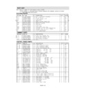
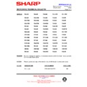
CABINET PARTS
ELECTRIC PARTS
REF NO
PART NO
§
DESCRIPTION
Q'TY
CODE
1-1
FH-DZA035WRE0
U
H.V. rectifier assembly
1
AP
1-2
FPWBFA308WRE2
U
Noise filter
1
AQ
1-3
QACCBA032WRE2
U
Power supply cord
1
AR
SW3
QSW-MA131WRE0
U
Stop switch
1
AK
MG
RV-MZA264WRE0
U
Magnetron
1
BK
C
RC-QZA222WRE0
U
High voltage capacitor
1
AT
SW2
QSW-MA131WRE0
U
Monitored latch switch
1
AK
SW1
QSW-MA133WRE0
U
Monitor switch
1
AN
FM
RMOTEA361WRE0
U
Fan motor
1
AT
F2
QFS-CA024WRE0
U
Fuse F8A
1
AC
OL
RLMPTA066WRE0
U
Oven lamp
1
AK
TTM
FMOTDA057WRK0
J
Turntable motor assy
1
AR
TC1
RTHM-A078WRE0
U
Thermal cut-out 125
°C (Magnetron)
1
AL
TC2
RTHM-A078WRE0
U
Thermal cut-out 125
°C (Oven)
1
AL
T
RTRN-A012URE0
U
Power transformer
1
BH
T1
RTRN-A529WRE0
U
T/C transformer
1
AV
REF NO
PART NO
§
DESCRIPTION
Q'TY
CODE
2-1
GCABUA024URP0
U
Outer case cabinet (SL)
1
AX
2-1
GCABUA469WRT0
U
Outer case cabinet (W)
1
AX
2-1
GCABUA005URP0
U
Outercase cabinet (G)
1
AX
2-2
GDAI-A219WRP5
U
Base plate assembly
1
AS
2-3
GLEGPA028WRE0
U
Foot
4
AA
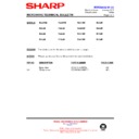
CONTROL PANEL PARTS
REF NO
PART NO
§
DESCRIPTION
Q'TY
CODE
∆
∆
∆
∆
3- 1
DPWBFA089URU0
U
Power unit
1
BH
3- 1A
QCNCMA430DRE0
U
3-pin connector (CN-A)
1
AC
3- 1B
QCNCMA414DRE0
U
2-pin connector (CN-B)
1
AB
3- 1C
QCNCMA230DRE0
U
4-pin connector (CN-E)
1
AC
3- 1D
QW-QZA008URE0
U
15 pin wire harness (WH-1)
1
AG
C1
VCKYD41HF104Z*
U
Capacitor 0.1 uF 50V
1
AC
C2
VCEAB31VW108M
U
Capacitor 1000 uF 35V
1
AE
C3
VCKYD41HF104Z*
U
Capacitor 0.1 uF 50V
1
AC
C4-5
VCEAB31VW106M+
U
Capacitor 10 uF 50V
2
AB
D1
RSRCDA013DRE0
U
Diode bridge (S1NB10)
1
AE
D5,6,8,12
VHD1SS270A/-1*
U
Diode (1SS270ATA)
4
AA
Q1-2
VS2SB1238//-3+
U
Transistor (2SB1238)
2
AD
Q3
VSKRC243M//-3+
U
Transistor (KRC243M)
1
AB
Q4
VS2SB1238//-3+
U
Transistor (2SB1238)
1
AD
R1
VRD-B12EF242J*
U
Resistor 2.4k ohm 1/4W
1
AA
R2
VRS-B13AA681J*
U
Resistor 680 ohm 1W
1
AB
R3
VRS-B13AA511J*
U
Resistor 510 ohm 1W
1
AB
R4
VRD-B12EF270J*
U
Resistor 27 ohm 1/4W
1
AA
R5
VRD-B12EF472J*
U
Resistor 4.7k ohm 1/4W
1
AA
R6
VRD-B12EF332J*
U
Resistor 3.3k ohm 1/4W
1
AA
R10
VRD-B12EF152J*
U
Resistor 1.5k ohm 1/4W
1
AA
RY2
RRLY-A092DRE0
U
Relay (VRB18-SH4)
1
AP
RY5
RRLY-A080DRE0
U
Relay (OJ-SH-124LM)
1
AG
SP1
RALM-A014DRE0
U
Buzzer (PKM22EPT-THAI)
1
AG
VRS1
RH-VZA034DRE0+
U
Varistor (10G471K)
1
AD
ZD1
VHEHZ161///-1*
U
Zener diode (HZ16-1)
1
AB
ZD3
VHEHZ201///-1*
U
Zener diode (HZ20-1)
1
AB
3- 2
DPWBFB934WRK0
U
CPU unit
1
BE
3- 3-1
FUNTKC067URE0
U
Key unit [R-362(G)M]
1
AS
3- 3-1
FUNTKC068URE0
U
Key unit [R-362(W)M]
1
AS
3- 3-1
FUNTKC070URE0
U
Key unit [R-362(SL)M]
1
AS
3- 3-2
HPNLCA028URF0
U
Control panel frame [R-362(W)M]
1
AN
3- 3-2
HPNLCA055URF0
U
Control panel frame [R-362(G)M]
1
AN
3- 3-2
HPNLCS004URR0
U
Control panel frame [R-362(SL)M]
1
AN
3- 3-3
JBTN-A017URF0
U
Open button [R-362(W)M]
1
AE
3- 3-3
JBTN-A061URF0
U
Open button [R-362(G)M]
1
AE
3- 3-3
JBTN-R005URF0
U
Open button [R-362(SL)M]
1
AE
3- 3-4
MSPRCA045WRE0
U
Open button spring
1
AA
3- 4
LHLD-A007URF0
U
LED holder
1
AC
3- 5
PSHEPA647WRE0
U
LED sheet
1
AL
3- 6
XEPSD30P10XS0
U
Screw; 3mm x 10mm
6
AA
R362M - 23
HOW TO ORDER REPLACEMENT PARTS
To have your order filled promptly and correctly, please furnish the following information.
1. MODEL NUMBER
2. REF. NO.
3. PART NO.
4. DESCRIPTION
*
*
*
*
*
∆
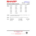
OVEN PARTS
REF NO
PART NO
§
DESCRIPTION
Q'TY
CODE
4-1
FOVN-A003URT0
U
Oven cavity
1
BL
4-2
LBNDKA107WRP1
U
Capacitor holder
1
AD
4-3
PHOK-A078WRF5
U
Latch hook
1
AH
4-4
NFANJA038WRE0
U
Fan blade assembly
1
AF
4-5
PDUC-A637WRF2
U
Fan duct
1
AL
4-6
LANGFA155WRP7
U
Chassis support
1
AF
4-7
PPACGA108WRE0
U
Packing
1
AC
4-8
LANGQA350WRP1
U
TTM support angle
1
AC
4-9
MLEVPA001URF3
U
Open lever
1
AE
4-10
NCPL-A042WRF1
U
Coupling
1
AD
4-11
PCOVPA308WRE1
U
Waveguide cover
1
AE
4-12
PFILWA042WRP0
U
Lamp filter
1
AB
4-14
PDUC-A606WRF0
U
Air intake duct
1
AK
4-15
PCUSGA317WRP0
U
Absorb cushion
2
AA
4-16
PCUSUA009URE0
U
Air deflector
1
AC
4-17
FDUC-A001URY0
U
Sensor duct assembly
1
AL
4-18
FDTCTA180WRK0
U
AH sensor assembly
1
AT
4-19
PCUSUA004URE0
U
Sensor cushion A
1
AC
4-20
PCUSUA005URE0
U
Sensor cushion B
1
AC
4-21
PDUC-A001URP0
U
Sensor duct
1
AG
4-22
XCBWW30P06000
U
Fastener
2
AA
4-23
PSPAGA001WRE0
U
Vib proof cushion
1
AA
4-24
PCUSGA372WRP0
U
HV tran cushion
1
AB
DOOR PARTS
REF NO
PART NO
§
DESCRIPTION
Q'TY
CODE
5-1
DDORFA749WRK0
U
Door panel assembly
1
AY
5-2
GCOVHA352WRF2
U
Choke cover
1
AH
5-3
GWAKPA075URR0
U
Door frame (W)
1
AR
5-3
GWAKPS010URR0
U
Door frame (SL)
1
AT
5-3
GWAKPA093URR0
U
Door frame (G)
1
AT
5-4
PGLSPA020URR0
U
Door screen
1
AX
5-5
LSTPPA147WRF1
U
Latch head
1
AE
5-6
MSPRTA141WRE0
U
Latch spring
1
AA
5-7
PSHEPA457WRE0
U
Door film
1
AF
5-8
FDORFA287WRT0
U
Door panel sub assembly
1
AW
5-9
XCPSD30P06000
J
Screw 3mm x 6mm
6
AA
5-10
LSTPPA003URF0
U
Glass stopper
1
AB
MISCELLANEOUS
REF NO
PART NO
§
DESCRIPTION
Q'TY
CODE
6-1
FROLPA062WRK0
U
Roller stay
1
AM
6-2
NTNT-A051WRE0
U
Turntable
1
AN
6-3
TINS-A146URR0
U
Instruction book
1
AS
6-4
QW-QZA014URE0
U
H.V. wire A
1
AB
6-5
QW-QZA210WRE1
U
H.V. wire B
1
AD
6-6
FW-VZA062URE0
U
Main wire harness
1
AR
6-7
TCAUHA001WRR1
U
Caution label
1
AC
6-9
FW-VZA053URE0
U
Stop switch harness
1
AF
SCREWS, NUTS AND WASHERS
REF NO
PART NO
§
DESCRIPTION
Q'TY
CODE
7-1
XWWSD50-06000
J
Washer
1
AA
7-2
XHTSD40P08RV0
J
Screw
4mm x 8mm
4
AA
7-3
XEPSD40P25000
J
Screw
4mm x 25mm
2
AA
7-4
LX-LZA011WRE0
U
Rivet
2
AB
7-5
XOTSD40P12RV0
J
Self tapping screw
20
AA
7-6
XHPSD40P08K00
J
Screw
4mm x 8mm
2
AA
7-7
XCPSD30P06000
J
Screw
3mm x 6mm
1
AA
7-8
XFPSD50P10KS0
J
Screw
4mm x 10mm
2
AB
7-9
XOTSF40P12000
U
Cabinet screw (black)
4
AA
7-9
XOTSE40P12000
J
Cabinet screw (silver)
4
AA
7-10
LX-NZA026WRE0
U
M4 Nloc nut
1
AA
Note: The parts marked ' ' have voltages in excess of 250V.
The parts marked ' ' may cause undue microwave exposure when damaged, loosened or removed.
'
'
§
' mark : Spare part delivery section.
PART LIST
R362M - 24
OVEN PARTS
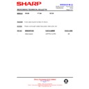
EXPLODED ILLUSTRATION
7.10
2-1
7-9
7-5
4-16
4-20
4-11
4-10
4-1
4-12
4-7
TTM
7-6
7-4
TC2
7-5
MG
4-4
4-3
7-5
SW2
SW1
C
4-2
SW3
1-1
7-2
6-1
6-2
7-5
4-14
4-9
7-1
T
7-8
7-5
4-15
2-2
2-3
7-5
4-23
4-24
OL
6-8
7-9
7-5
TC1
7-7
7-9
F2
7-6
1-2
7-2
1-3
4-6
1-3
4-5
FM
7-3
7-2
x 4
x2
7-5
7-5
T1
7-2
7-2
R362M - 25
EXPLODED ILLUSTRATION
CONTROL PANEL PARTS
DOOR PARTS
3-3-1
3-3-2
3-3-3
3-3-4
3 - 3
3 - 2
3 - 1
3 - 6
3 - 6
3 - 6
3 - 4
3 - 5
5-9
5-9
5-4
5-3
5-1
5-8
5-2
5-5
5-6
5-7
5-10

