Read Sharp R-246 (serv.man3) Parts Guide online
26
R-246(G)
R-246(SL)
R-246(W)
R-246(SL)
R-246(W)
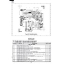
Figure S-3. Printed Wiring Board
1
A
B
C
D
E
F
G
H
A
B
C
D
E
F
G
H
2
3
4
5
6
1
2
3
4
5
6
*
*
*
*
*
*
*
*
∆
*
*
PARTS LIST
ELECTRIC PARTS
1- 1
QACC-A088WRE0
Power supply cord
1
AW
1- 2
FPWBFA347WRKZ
Noise filter
1
AX
1- 3
FH-DZA103WRKZ
High voltage rectifier
1
AS
1- 3
FH-DZA082WRK0
High voltage rectifier (Interchangeable)
1
AQ
1- 3
FH-DZA087WRK0
High voltage rectifier (Interchangeable)
1
AQ
1- 4
QSW-MA085WRE0
Monitored latch switch
1
AF
1- 4
QSW-MA137WRE0
Monitored latch switch (Interchangeable)
1
AH
1- 5
QSW-MA086WRE0
Monitor switch
1
AF
1- 5
QSW-MA138WRE0
Monitor switch (Interchangeable)
1
AH
1- 6
QSW-MA085WRE0
2nd. interlock relay control switch
1
AF
1- 6
QSW-MA137WRE0
2nd. interlock relay control switch (Interchangeable)
1
AH
1- 7
RC-QZA295WRZZ
High voltage capacitor
1
AV
1- 7
RC-QZA218WRE0
High voltage capacitor (Interchangeable)
for production use
1
--
1- 8
RMOTEA403WRZZ
Fan motor
1
AZ
1- 8
RMOTEA340WRE0
Fan motor (Interchangeable)
1
AX
1- 8
RMOTEA389WRE0
Fan motor (Interchangeable) for production use
1
AX
1- 9
RV-MZA306WRZZ
Magnetron
1
BL
1-10
RLMPTA083WRZZ
Oven lamp
1
AM
1-11
RMOTDA173WRE0
Turntable motor
1
AX
1-11
RMOTDA226WRE0
Turntable motor (Interchangeable)
1
AT
1-12
RTHM-A116WRE0
Thermal cut-out 125˚C (OVEN)
1
AK
1-12
RTHM-A078WRE0
Thermal cut-out 125˚C (OVEN) (Interchangeable)
1
AK
1-13
RTRN-A679WRZZ
High voltage transformer
1
BK
Note: The parts marked "
∆
" may cause undue microwave exposure.
The parts marked "*" are used in voltage more than 250V.
REF. NO.
PART NO.
DESCRIPTION
Q'TY
CODE
3
DIP
,F
CHIP SIDE
R4
C2
D3
C1
C21
Q21
D1
D2
D4
Q22
VRS1
D40
B
B
1
1
1
7
S
P
4
3
2
2
E
E
R30
D22
(R21)
1
3
RY1
RY2
D20
(ZD2)
CN - B
CN - A
SP1
C8
(Q23)
B
E
D21
(J2)
R-246(G)
R-246(SL)
R-246(W)
R-246(SL)
R-246(W)
27
REF. NO.
PART NO.
DESCRIPTION
Q'TY
CODE
1-14
QFS-IA004WRE0
High voltage fuse 0.6A
1
AK
1-15
QFS-CA027WRZZ
Fuse T6.3A
1
AG
1-16
RTHM-A117WRE0
Thermal cut-out 95˚C (MG)
1
AK
1-16
RTHM-A079WRE0
Thermal cut-out 95˚C (MG) (Interchangeable)
1
AH
CABINET PARTS
2- 1
GCABUA870WRPZ
Outer case cabinet [R-246(G)]
1
BD
2- 1
GCABUA871WRPZ
Outer case cabinet [R-246(SL)]
1
BD
2- 1
GCABUA824WRPZ
Outer case cabinet [R-246(W)]
1
BG
2- 2
GDAI-A304WRW0
Bottom plate
1
AF
2- 3
GLEGPA074WRE0
Foot
2
AC
CONTROL PANEL PARTS
3- 1
DPWBFC266WRUZ
Control unit
1
BE
3- 2
FPNLCB651WRKZ
Control panel frame with key unit [R-246(W)]
1
BB
3- 2
FPNLCB652WRKZ
Control panel frame with key unit [R-246(SL)]
1
BB
3- 2
FPNLCB653WRKZ
Control panel frame with key unit [R-246(G)]
1
BB
3- 2-1
FUNTKB118WREZ
Key unit [R-246(W)]
1
AX
3- 2-1
FUNTKB119WREZ
Key unit [R-246(SL)]
1
AX
3- 2-1
FUNTKB120WREZ
Key unit [R-246(G)]
1
AX
3- 3
QCNC-A013WRZZ
Rubber connector
1
AE
3- 4
RLCDSA062DRE0
Liquid crystal display
1
AM
3- 5
XEPSD30P08XS0
Screw; Control unit mtg.
3
AA
OVEN PARTS
4- 1
PHOK-A127WRFZ
Latch hook
1
AL
4- 2
LANGQA530WRWZ
Light mount plate
1
AP
4- 3
PCUSUA502WRP0
Waterproof cushion
1
AD
4- 4
LBNDKA038WRP0
Capacitor holder
1
AF
4- 5
NFANJA029WRE0
Fan blade
1
AK
4- 6
PDUC-A694WRF0
Fan duct
1
AG
4- 7
FOVN-A457WRTZ
Oven cavity
1
BD
4- 8
GLEGPA073WRF0
Leg
1
AD
4- 9
LANGTA318WRP0
Chassis support
1
AE
4-10
PCUSGA534WRP0
Cushion
1
AF
4-11
PCOVPA276WRE0
Waveguide cover
1
AM
4-12
PCUSUA500WRP0
Cushion
1
AC
4-13
PPACGA097WRE0
O-ring
1
AG
4-14
PCUSUA443WRP0
Cushion
2
AE
DOOR PARTS
5- 1
FDORFA321WRT0
Door panel
1
AT
5- 2
GWAKPA863WRFZ
Door frame [R-246(G)]
1
AW
5- 2
GWAKPA861WRTZ
Door frame [R-246(SL)]
1
AW
5- 2
GWAKPA628WRF0
Door frame [R-246(W)]
1
AY
5- 3
HPNL-A780WRRZ
Door screen
1
AV
5- 4
LSTPPA175WRF0
Latch head
1
AE
5- 5
MSPRTA084WRE0
Latch spring
1
AB
5- 6
PSHEPA622WRE0
Sealer film
1
AG
5- 7
GCOVHA390WRF0
Choke cover
1
AK
5- 8
XCPSD40P08000
Screw : 4mm x 8mm
4
AA
MISCLANEOUS
6- 1
FROLPA090WRK0
Turntable support
1
AQ
6- 2
NTNT-A107WREZ
Turntable
1
AU
6- 3
TINSEA945WRRZ
Instruction book
1
AP
6- 4
FW-VZB762WRE0
Switch harness
1
AT
6- 5
FW-VZB924WREZ
Main wire harness
1
AU
6- 6
TCAUHA214WRR0
K caution label
1
AC
SCREWS AND WASHERS
7- 1
XHPSD40P08K00
Screw : 4mm x 8mm
4
AC
7- 2
LX-EZA042WRE0
Special screw
2
AB
7- 3
LX-WZA028WRE0
Special washer
1
AB
7- 4
XOTSF40P08000
Screw : 4mm x 8mm [R-246(G)]
4
AA
7- 4
XOTSE40P08000
Screw : 4mm x 8mm [R-246(SL)][R-246(W)]
4
AA
7- 5
XHTSD40P08RV0
Screw : 4mm x 8mm
5
AA
7- 6
XHPSD30P06000
Screw : 3mm x 6mm
1
AA
7- 7
XOTSD40P12RV0
Screw : 4mm x 12mm
9
AA
7- 8
XOTSD40P08000
Screw : 4mm x 8mm
5
AA
7- 9
LX-CZ0052WRE0
Special screw
2
AA
7-10
XHPSD40P08000
Screw : 4mm x 8mm
3
AA
*
HOW TO ORDER REPLACEMENT PARTS
To have your order filled prompty and correctly, please furnish the following information.
1. MODEL NUMBER
2. REF. NO.
3. PART NO.
4. DESCRIPTION
∆
∆
∆
∆
∆
∆
∆
28
R-246(G)
R-246(SL)
R-246(W)
R-246(SL)
R-246(W)
OVEN PARTS
1
A
B
C
D
E
F
G
H
A
B
C
D
E
F
G
H
2
3
4
5
6
1
2
3
4
5
6
7-7
2-1
7-7
7-7
7-7
7-4
7-5
4-6
1-2
1-15
4-4
1-14
4-9
7-1
7-8
7-9
7-1
1-13
7-7
7-7
7-7
4-1
2-2
7-7
2-3
2-3
7-8
7-2
4-13
7-3
1-11
7-5
1-8
1-6
1-4
1-5
1-7
1-3
7-4
7-1
7-10
7-1
1-9
1-12
1-16
4-10
4-7
4-11
6-2
6-1
4-8
6-6
1-1
4-5
7-6
4-12
4-14
4-14
7-8
4-3
7-8
1-10
4-2
R-246(G)
R-246(SL)
R-246(W)
R-246(SL)
R-246(W)
29
CONTROL PANEL PARTS
DOOR PARTS
MISCELLANEOUS
1
A
B
C
D
E
F
G
H
A
B
C
D
E
F
G
H
2
3
4
5
6
1
2
3
4
5
6
5-3
5-5
5-2
5-4
5-8
5-8
6-5
6-4
5-6
5-7
5-1
Actual wire harness may be different than illustration.
3-2
3-3
3-4
3-1
3-5
Before attaching Control unit to
Control panel, foil side of Control
unit must be cleaned by ethyl-
alcohol.
Control panel, foil side of Control
unit must be cleaned by ethyl-
alcohol.
3-2-1


